Werner’s theory of Coordination Compounds

Find free online Chemistry Topics covering a broad range of concepts from research institutes around the world.

Werner’s theory of Coordination Compounds

Swiss chemist Alfred Werner was the first one to propose a theory of coordination compounds to explain the observed behaviour of them. Let us consider the different coloured complexes of cobalt (III) chloride with ammonia which exhibit different properties as shown below.

Werner’S Theory of Coordination Compounds img 1

In this case, the valences of the elements present in both the reacting molecules, cobalt (III) chloride and ammonia are completely satisfied. Yet these substances react to form the above mentioned complexes.

To explain this behaviour Werner postulated his theory as follows:

1. Most of the elements exhibit, two types of valence namely primary valence and secondary valence and each element tend to satisfy both the valences. In modern terminology, the primary valence is referred as the oxidation state of the metal atom and the secondary valence as the coordination number. For example, according to Werner, the primary and secondary valences of cobalt are 3 and 6 respectively.

2. The primary valence of a metal ion is positive in most of the cases and zero in certain cases. They are always satisfied by negative ions. For example in the complex CoCl3.6NH3, The primary valence of Co is +3 and is satisfied by 3Cl ions.

3. The secondary valence is satisfied by negative ions, neutral molecules, positive ions or the combination of these. For example, in CoCl3.6NH3 the secondary valence of cobalt is 6 and is satisfied by six neutral ammonia molecules, whereas in CoCl3.5NH3 the secondary valence of cobalt is satisfied by five neutral ammonia molecules and a Cl ion.

4. According to Werner, there are two spheres of attraction around a metal atom/ion in a complex. The inner sphere is known as coordination sphere and the groups present in this sphere are firmly attached to the metal. The outer sphere is called ionisation sphere. The groups present in this sphere are loosely bound to the central metal ion and hence can be separated into ions upon dissolving the complex in a suitable solvent.

Werner’S Theory of Coordination Compounds img 2

1. The primary valences are non-directional while the secondary valences are directional. The geometry of the complex is determined by the spacial arrangement of the groups which satisfy the secondary valence. For example, if a metal ion has a secondary valence of six, it has an octahedral geometry. If the secondary valence is 4, it has either tetrahedral or square planar geometry.

The following table illustrates the Werner’s postulates.

Werner’S Theory of Coordination Compounds img 3

Limitations of Werner’s Theory:

Even though, Werner’s theory was able to explain a number of properties of coordination compounds, it does not explain their colour and the magnetic properties.

Important Compound of Transition Elements

Find free online Chemistry Topics covering a broad range of concepts from research institutes around the world.

Important Compound of Transition Elements

Oxides and Oxoanions of Metals

Generally, transition metal oxides are formed by the reaction of transition metals with molecular oxygen at high temperatures. Except the first member of 3d series, Scandium, all other transition elements form ionic metal oxides. The oxidation number of metal in metal oxides ranges from +2 to +7. As the oxidation number of a metal increases, ionic character decreases, for example, Mn2O7 is covalent.

Mostly higher oxides are acidic in nature, Mn2O7 dissolves in water to give permanganic acid (HMnO4), similarly CrO3 gives chromic acid (H2CrO4) and dichromic acid (H2Cr2O7). Generally lower oxides may be amphoteric or basic, for example, Chromium (III) oxide – Cr2O3, is amphoteric and Chromium(II) oxide, CrO, is basic in nature.

Potassium Dichromate K2Cr2O7

Preparation:

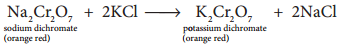
Potassium dichromate is prepared from chromate ore. The ore is concentrated by gravity separation. It is then mixed with excess sodium carbonate and lime and roasted in a reverbratory furnace.

Important Compound of Transition Elements img 1

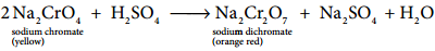
The roasted mass is treated with water to separate soluble sodium chromate from insoluble iron oxide. The yellow solution of sodium chromate is treated with concentrated sulphuric acid which converts sodium chromate into sodium dichromate.

Important Compound of Transition Elements img 2

The above solution is concentrated to remove less soluble sodium sulphate. The resulting solution is filtered and further concentrated. It is cooled to get the crystals of Na2SO4.2H2O.

The saturated solution of sodium dichromate in water is mixed with KCl and then concentrated to get crystals of NaCl. It is filtered while hot and the filtrate is cooled to obtain K2Cr2O7 crystals.

Important Compound of Transition Elements img 3

Physical Properties:

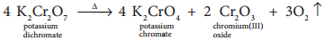
Potassium dichromate is an orange red crystalline solid which melts at 671K and it is moderately soluble in cold water, but very much soluble in hot water. On heating it decomposes and forms Cr2O3 and molecular oxygen. As it emits toxic chromium fumes upon heating, it is mainly replaced by sodium dichromate.

Important Compound of Transition Elements img 4

Structure of Dichromate Ion:

Both chromate and dichromate ion are oxo anions of chromium and they are moderately strong oxidizing agents. In these ions chromium is in +6 oxidation state. In an aqueous solution, chromate and dichromate ions can be interconvertible, and in an alkaline solution chromate ion is predominant, whereas dichromate ion becomes predominant in acidic solutions. Structures of these ions are shown in the figure.

Important Compound of Transition Elements img 5

Chemical Properties:

1. Oxidation

Potassium dichromate is a powerful oxidising agent in acidic medium. Its oxidising action in the presence of H+ ions is shown below. You can note that the change in the oxidation state of chromium from Cr6+ to Cr3+. Its oxidising action is shown below.

Cr2O72- + 14H+ + 6e → 2Cr3+ + 7H2O

The oxidising nature of potassium dichromate (dichromate ion) is illustrated in the following examples.

(i) It oxidises ferrous salts to ferric salts.

Cr2O72- + 6Fe2+ + 14H+ → 2Cr3+ + 6Fe3+ + 7H2O

(ii) It oxidises iodide ions to iodine

Cr2O72- + 6I + 14H+ → 2Cr3+ + 3I2 + 7H2O

(iii) It oxidises sulphide ion to sulphur

Cr2O72- + 3S2- + 14H+ → 2Cr3+ + 3S + 7H2O

(iv) It oxidises sulphur dioxide to sulphate ion

Cr2O72- + 3SO2 + 2H+ → 2Cr3+ + 3SO2-4 + H2O

(v) It oxidises stannous salts to stannic salt

Cr2O72- + 3Sn2+ + 14H+ → 2Cr3+ + 3Sn4+ + 7H2O

(vi) It oxidises alcohols to acids.

2K2Cr2O7 + 8H2SO4 + 3CH3CH2OH →
2K2SO4 + 2Cr2(SO4)3 + 3CH3COOH + 11H2O

Chromyl Chloride Test:

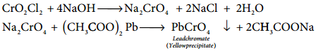
When potassium dichromate is heated with any chloride salt in the presence of Conc H2SO4, orange red vapours of chromyl chloride (CrO2Cl2) is evolved. This reaction is used to confirm the presence of chloride ion in inorganic qualitative analysis.

Important Compound of Transition Elements img 6

The chromyl chloride vapours are dissolved in sodium hydroxide solution and then acidified with acetic acid and treated with lead acetate. A yellow precipitate of lead chromate is obtained.

CrO2Cl2 + 4NaOH → Na2CrO4 + 2NaCl + 2H2O

Important Compound of Transition Elements img 7

Uses of Potassium Dichromate:

Some important uses of potassium dichromate are listed below.

  1. It is used as a strong oxidizing agent.
  2. It is used in dyeing and printing.
  3. It used in leather tanneries for chrome tanning.
  4. It is used in quantitative analysis for the estimation of iron compounds and iodides.

Potassium Permanganate – KMnO4

Preparation:
Potassium permanganate is prepared from pyrolusite (MnO2) ore. The preparation involves the following steps.

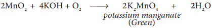
(i) Conversion of MnO2 to potassium manganate:

Powdered ore is fused with KOH in the presence of air or oxidising agents like KNO3 or KClO3. A green coloured potassium manganate is formed.

Important Compound of Transition Elements img 8

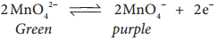
(ii) Oxidation of potassium manganate to potassium permanganate:

Potassium manganate thus obtained can be oxidised in two ways, either by chemical oxidation or electrolytic oxidation.

Chemical Oxidation:

In this method potassium manganate is treated with ozone (O3) or chlorine to get potassium permanganate.

2MnO42- + O3 + H2O → 2MnO4 + 2OH + O2
2MnO42- + Cl2 → 2MnO4 + 2Cl

Electrolytic Oxidation

In this method aqueous solution of potassium manganate is electrolyzed in the presence of little alkali.

K2MnO4 ⇄ 2K+ + MnO42-
H2O ⇄ H+ + OH

Manganate ions are converted into permanganate ions at anode.

Important Compound of Transition Elements img 9

H2 is liberated at the cathode.

2H+ + 2e → H2

The purple coloured solution is concentrated by evaporation and forms crystals of potassium permanganate on cooling.

Physical Properties:

Potassium permanganate exists in the form of dark purple crystals which melts at 513 K. It is sparingly soluble in cold water but, fairly soluble in hot water.

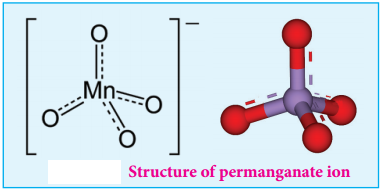
Structure of Permanganate ion

Permanganate ion has tetrahedral geometry in which the central Mn7+ is sp3 hybridised.

Important Compound of Transition Elements img 10

Chemical Properties:

1. Action of Heat:

When heated, potassium permanganate decomposes to form potassium manganate and manganese dioxide.

2KMnO4 → 2K2MnO4 + MnO2 + O2

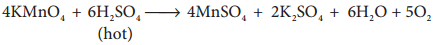
2. Action of conc H2SO4

On treating with cold conc H2SO4, it decomposes to form manganese heptoxide, which subsequently decomposes explosively.

Important Compound of Transition Elements img 11

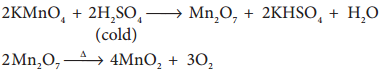
But with hot conc H2SO4, Potassium permanganate give MnSO4. 

Important Compound of Transition Elements img 12

3. Oxidising Property:

Potassium permanganate is a strong oxidising agent, its oxidising action differs in different reaction medium.

(a) In neutral medium:

In neutral medium, it is reduced to MnO2

MnO4 + 2H2O + 3e → MnO2 + 4OH

(i) It oxidises H2S to sulphur

2MnO4 + 2H2O + 3e → MnO2 + 4OH

(ii) It oxidises thiosulphate into sulphate

8MnO4 + 3S2O32- + H2O → 6SO42- + 8MnO2 + 2OH

(b) In alkaline medium:

In the presence of alkali metal hydroxides, the permanganate ion is converted into manganate.

MnO4 + e → MnO42-

This manganate is further reduced to MnO2 by some reducing agents.

MnO42- + H2O → MnO2 + 2OH + [O]

So the overall reaction can be written as follows.

MnO4 + 2H2O + 3e → MnO2 + 4OH

This reaction is similar as that for neutral medium.

Bayer’s Reagent:

Cold dilute alkaline KMnO4 is known as Bayer’s reagent. It is used to oxidise alkenes into diols. For example, ethylene can be converted into ethylene glycol and this reaction is used as a test for unsaturation.

(c) In acid medium:

In the presence of dilute sulphuric acid, potassium permanganate acts as a very strong oxidising agent. Permanganate ion is converted into Mn2+ ion.

MnO4 + 8H+ + 5e → Mn2+ + 4H2O

The oxidising nature of potassium permanganate (permanganate ion) in acid medium is illustrated in the following examples.

(i) It oxidises ferrous salts to ferric salts.

2MnO4 + 10Fe2+ + 16H+ → 2Mn2+ + 10Fe3+ + 8H2O

(ii) It oxidises iodide ions to iodine

2MnO4 + 10 I + 16H+ → 2Mn2+ + 5I2 + 8H2O

(iii) It oxidises oxalic acid to CO2

2MnO4 + 5(COO)2-2 + 16H+ → 2Mn2+ + 10CO2 + 8H2O

(iv) It oxidises sulphide ion to sulphur

2MnO4 + 5 S2- + 16H+ → 2Mn2+ + 5 S + 8H2O

(v) It oxidises nitrites to nitrates

2MnO4 + 5 NO2 + 6H+ → 2Mn2+ + 5NO3 + 3H2O

(vi) It oxidises alcohols to aldehydes.

2KMnO4 + 3H2SO4 + 5CH3CH2OH → K2SO4 + 2MnSO4 + 5CH3CHO + 8H2O

(vii) It oxidises sulphite to sulphate

2MnO4 + 5SO32- + 6H+ → 2Mn2+ + 5SO42- + 3H2O

Uses of Potassium Permanganate:

Some important uses of potassium permanganate are listed below.

  1. It is used as a strong oxidizing agent.
  2. It is used for the treatment of various skin infections and fungal infections of the foot.
  3. It used in water treatment industries to remove iron and hydrogen sulphide from well water.
  4. It is used as Bayer’s reagent for detecting unsaturation in an organic compound.
  5. It is used in quantitative analysis for the estimation of ferrous salts, oxalates, hydrogen peroxide and iodides.

F-Block Elements – Inner Transition Elements

In the inner transition elements there are two series of elements.

  1. Lanthanoids (previously called lanthanides)
  2. Actinoids (previously called actinides)

Lanthanoid series consists of fourteen elements from Cerium (58Ce) to Lutetium (71Lu) following Lanthanum (57La). These elements are characterised by the preferential filling of 4f orbitals, Similarly actinoids consists of 14 elements from Thrium (90Th) to Lawrencium (103Lr) following Actinium (89Ac). These elements are characterised by the preferential filling of 5f orbital.

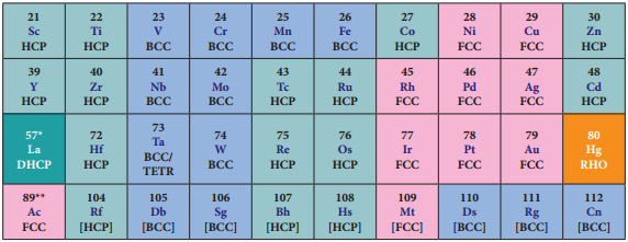
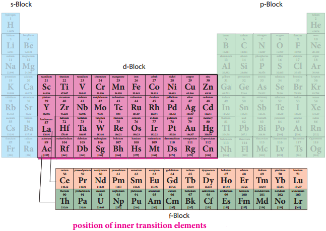
The position of Lanthanoids in the periodic table

The actual position of Lanthanoids in the periodic table is at group number 3 and period number 6. However, in the sixth period after lanthanum, the electrons are preferentially filled in inner 4f sub shell and these fourteen elements following lanthanum show similar chemical properties. Therefore these elements are grouped together and placed at the bottom of the periodic table. This position can be justified as follows.

  1. Lanthanoids have general electronic configuration [Xe] 4f1-14 5d10-1 6s2
  2. The common oxidation state of lanthanoides is +3
  3. All these elements have similar physical and chemical properties.

Similarly the fourteen elements following actinium resemble in their physical and chemical properties. If we place these elements after Lanthanum in the periodic table below 4d series, the properties of the elements belongs to a group would be different and it would affect the proper structure of the periodic table. Hence a separate position is provided to the inner transition elements as shown in the figure.

Important Compound of Transition Elements img 13

Electronic Configuration of Lanthanoids:

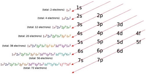
We know that the electrons are filled in different orbitals in the order of their increasing energy in accordance with Aufbau principle. As per this rule after filling 5s, 5p and 6s and 4f level begin to fill from lanthanum, and hence the expected electronic configuration of Lanthanum(La) is [Xe] 4f1 5d° 6s2 but the actual electronic configuration of Lanthanum is [Xe] 4f° 5d1 6s2 and it belongs to d block.

Filling of 4f orbital starts from Cerium (Ce) and its electronic configuration is [Xe] 4f1 5d1 6s2. As we move from Cerium to other elements the additional electrons are progressively filled in 4f orbitals as shown in the table.

Table: Electronic Configuration of Lanthanum and Lanthanoids

Important Compound of Transition Elements img 14

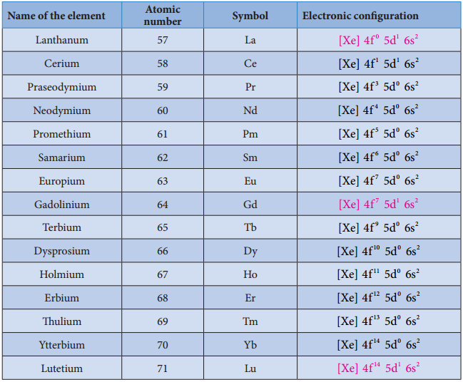
In Gadolinium (Gd) and Lutetium (Lu) the 4f orbitals, are half-filled and completely filled, and one electron enters 5d orbitals. Hence the general electronic configuration of 4f series of elements can be written as [Xe] 4f1-14 5d0-1 6s2

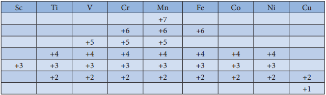
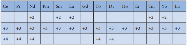
Oxidation State of Lanthanoids:

The common oxidation state of lanthanoids is +3. In addition to that some of the lanthanoids also show either +2 or +4 oxidation states. Gd3+ and Lu3+ ions have extra stability, it is due to the fact that they have exactly half filled and completely filled f-orbitals respectively their electronic configurations are

Gd3+: [Xe]4f7
Lu3+: [Xe]4f14

Similarly Cerium and terbium attain 4f° and 4f7 configurations respectively in the +4 oxidation states. Eu2+
and Yb2+ ions have exactly half filled and completely filled f orbitals respectively.

The stability of different oxidation states has an impact on the properties of these elements the following table shows the different oxidation states of lanthanoids.

Important Compound of Transition Elements img 15

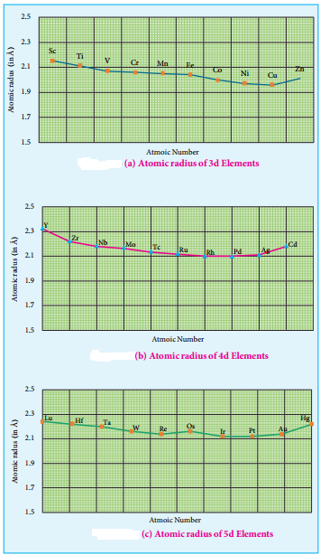
Atomic and Ionic Radii:

As we move across 4f series, the atomic and ionic radii of lanthanoids show gradual decrease with increse in atomic number. This decrease in ionic size is called lanthanoid contraction.

Important Compound of Transition Elements img 16

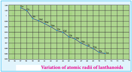
Cause of Lanthanoid Contraction:

As we move from one element to another in 4f series (Ce to Lu) the nuclear charge increases by one unit and an additional electron is added into the same inner 4f sub shell. We know that 4f sub shell have a diffused shapes and therefore the shielding effect of 4f elelctrons relatively poor hence, with increase of nuclear charge, the valence shell is pulled slightly towards nucleus. As a result, the effective nuclear charge experienced by the 4f elelctorns increases and the size of Ln3+ ions decreases. Lanthanoid contraction of various lanthanoids is shown in the graph.

Consequences of Lanthanoid Contraction:

1. Basicity Differences

As we from Ce3+ to Lu3+, the basic character of Ln3+ ions decrease. Due to the decrease in the size of Ln3+ ions, the ionic character of Ln – OH bond decreases (covalent character increases) which results in the decrease in the basicity.

2. Similarities Among Lanthanoids:

In the complete f – series only 10 pm decrease in atomic radii and 20 pm decrease in ionic radii is observed because of this very small change in radii of lanthanoids, their chemical properties are quite similar.

The elements of the second and third transition series resemble each other more closely than the elements of the first and second transition series. For example

Series

Element

Atomic Radius

3d SeriesTi132 pm
4d SeriesZr145 pm
5d SeriesHf144 pm

Actinoids:

The fourteen elements following actinium, i.e., from thorium (Th to lawrentium (Lr) are called actinoids. Unlike the lanthanoids, all the actinoids are radioactive and most of them have short half lives. Only thorium and uranium (U) occur in significant amount in nature and a trace amounts of Plutonium (Pu) is also found in Uranium ores. Neptunium (Np) and successive heavier elements are produced synthetically by the artificial transformation of naturally occuring elements by nuclear reactions. Similar to lanthanoids, they are placed at the bottom of the periodic table.

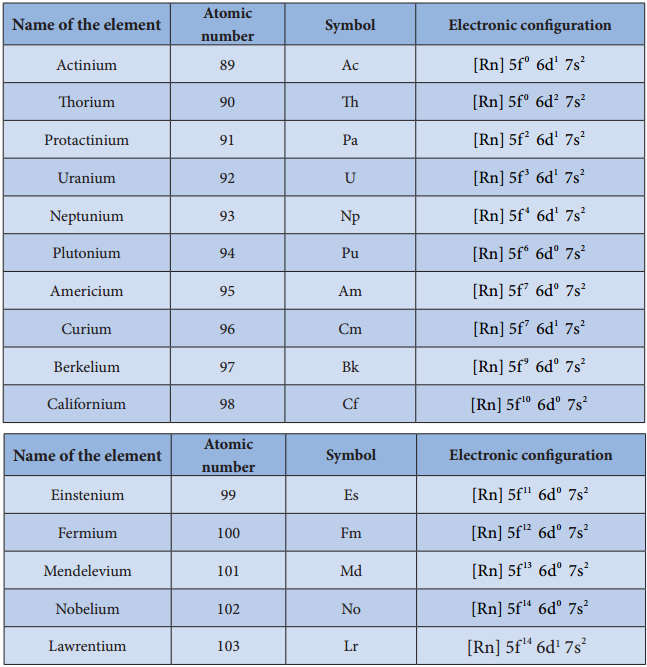
Electronic Configuration:

The electronic configuration of actinoids is not definite. The general valence shell electronic configuration of 5f elements is represented as [Rn]5f1-146d0-27s2. The following table show the electronic configuration of actinoids.

Table: Electronic configuration of actinoids

Important Compound of Transition Elements img 17

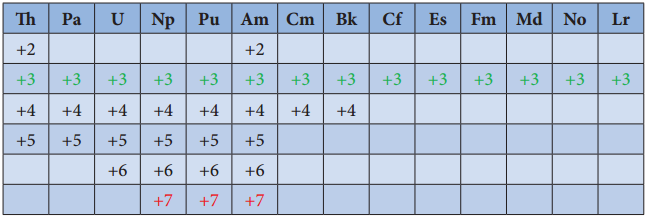
Oxidation State of Actinoids:

Like lanthanoids, the most common state of actinoids is +3. In addition to that actinoids show variable oxidation states such as +2 , +3 , +4 ,+5,+6 and +7. The elements Americium(Am) and Thrium (Th show +2 oxidation state in some compounds, for example thorium iodide (ThI2). The elements T, Pa, U, Np, Pu and Am show +5 oxidation states. Np and Pu exhibit +7 oxidation state.

Important Compound of Transition Elements img 18

Differences Between Lanthanoids and Actinoids:

Lanthanoids

Actinoids

1. Differentiating electron enters in 4f orbital1. Differentiating electron enters in 5f orbital
2. Binding energy of 4f orbitals are higher2. Binding energy of 5f orbitals are lower
3. They show less tendency to form complexes3. They show greater tendency to form complexes
4. Most of the lanthanoids are colourless4. Most of the actinoids are coloured. For example.
U3+(red), U4+(green), UO22+(yellow)
5. They do not form oxo cations5. They do form oxo cations such as UO22+, NPO22+ etc
6. Besides +3 oxidation states lanthanoids show +2 and +4 oxidation states in few cases6. Besides +3 oxidation states actinoids show higher oxidation states such as +4, +5, +6 and +7

General Trend in Properties

Find free online Chemistry Topics covering a broad range of concepts from research institutes around the world.

General Trend in Properties

Metallic Behaviour:

All the transition elements are metals. Similar to all metals the transition metals are good conductors of heat and electricity. Unlike the metals of Group-1 and group-2, all the transition metals except group 11 elements are hard. Of all the known elements, silver has the highest electrical conductivity at room temperature. Most of the transition elements are hexagonal close packed, cubic close packed or body centrered cubic which are the characteristics of true metals.

Figure 4.2 Lattice Structures of 3d, 4d, and 5d transistion metals

General Trend in Properties img 1

As we move from left to right along the transition metal series, melting point first increases as the number of unpaired d electrons available for metallic bonding increases, reach a maximum value and then decreases, as the d electrons pair up and become less available for bonding.

For example, in the first series the melting point increases from Scandium (m.pt 1814K) to a maximum of 2183 K for vanadium, which is close to 2180K for chromium. However, manganese in 3d series and Tc in 4d series have low melting point. The maximum melting point at about the middle of transition metal series indicates that d5 configuration is favourable for strong interatomic attraction. The following figure shows the trends in melting points of transition elements.

General Trend in Properties img 2

Variation of Atomic and Ionic Size:

It is generally expected a steady decrease in atomic radius along a period as the nuclear charge increases and the extra electrons are added to the same sub shell. But for the 3d transition elements, the expected decrease in atomic radius is observed from Sc to V, thereafter up to Cu the atomic radius nearly remains the same.

As we move from Sc to Zn in 3d series the extra electrons are added to the 3d orbitals, the added 3d electrons only partially shield the increased nuclear charge and hence the effective nuclear charge increases slightly. However, the extra electrons added to the 3d sub shell strongly repel the 4s electrons and these two forces are operated in opposite direction and as they tend to balance each other, it leads to constancy in atomic radii.

General Trend in Properties img 3

At the end of the series, d – orbitals of Zinc contain 10 electrons in which the repulsive interaction between the electrons is more than the effective nuclear charge and hence, the orbitals slightly expand and atomic radius slightly increases. Generally as we move down a group atomic radius increases, the same trend is expected in d block elements also. As the electrons are added to the 4d sub shell, the atomic radii of the 4d elements are higher than the corresponding elements of the 3d series.

However there is an unexpected observation in the atomic radius of 5d elements which have nearly same atomic radius as that of corresponding 4d elements. T is is due to lanthanoide contraction which is to be discussed later in this unit under inner transition elements.

Ionization Enthalpy:

Ionization energy of transition element is intermediate between those of s and p block elements. As we move from left to right in a transition metal series, the ionization enthalpy increases as expected. This is due to increase in nuclear charge corresponding to the filling of d electrons. The following figure show the trends in ionisation enthalpy of transition elements.

General Trend in Properties img 4

The increase in first ionisation enthalpy with increase in atomic number along a particular series is not regular. The added electron enters (n-1)d orbital and the inner electrons act as a shield and decrease the effect of nuclear charge on valence ns electrons. Therefore, it leads to variation in the ionization energy values.

The ionisation enthalpy values can be used to predict the thermodynamic stability of their compounds. Let us compare the ionisation energy required to form Ni2+ and Pt2+ ions.

For Nickel, IE1 + IE2
= (735 + 1753)
= 2490 kJmol-1

For Platinum, IE1 + IE2
= (864 + 1791)
= 2655 kJmol-1

Since, the energy required to form Ni2+ is less than that of Pt2+, Ni(II) compounds are thermodynamically more stable than Pt(II) compounds.

Oxidation State:

The first transition metal Scandium exhibits only +3 oxidation state, but all other transition elements exhibit variable oxidation states by loosing electrons from (n-1)d orbital and ns orbital as the energy difference between them is very small. Let us consider the 3d series; the following table summarizes the oxidation states of the 3d series elements.

General Trend in Properties img 5

At the beginning of the series, +3 oxidation state is stable but towards the end +2 oxidation state becomes stable. The number of oxidation states increases with the number of electrons available, and it decreases as the number of paired electrons increases.

Hence, the first and last elements show less number of oxidation states and the middle elements with more number of oxidation states. For example, the first element Sc has only one oxidation state +3; the middle element Mn has six different oxidation states from +2 to +7. The last element Cu shows +1 and +2 oxidation states only.

The relative stability of different oxidation states of 3d metals is correlated with the extra stability of half filled and fully filled electronic confiurations. Example: Mn2+(3d5) is more stable than Mn4+(3d3)

The oxidation states of 4d and 5d metals vary from +3 for Y and La to +8 for Ru and Os. The highest oxidation state of 4d and 5d elements are found in their compounds with the higher electronegative elements like O, F and Cl. for example: RuO4, OsO4 and WCl6. Generally in going down a group, a stability of the higher oxidation state increases while that of lower oxidation state decreases.

It is evident from the Frost diagram (ΔG° vs oxidation number) as shown below. For titanium, vanadium and chromium, the most thermodynamically stable oxidation state is +3. For iron, the stabilities of +3 and +2 oxidation states are similar. Copper is unique in 3d series having a stable +1 oxidation state. It is prone to disproportionate to the +2 and 0 oxidation states.

Standard Electrode Potentials of Transition Metals

Redox reactions involve transfer of electrons from one reactant to another. Such reactions are always coupled, which means that when one substance is oxidised, another must be reduced. The substance which is oxidised is a reducing agent and the one which is reduced is an oxidizing agent. The oxidizing and reducing power of an element is measured in terms of the standard electrode potentials.

General Trend in Properties img 6

Standard electrode potential is the value of the standard emf of a cell in which molecular hydrogen under standard pressure (1 atm) and temperature (273 K) is oxidised to solvated protons at the electrode. If the standard electrode potential (E°), of a metal is large and negative, the metal is a powerful reducing agent, because it loses electrons easily. Standard electrode potentials (reduction potential) of few first transition metals are given in the following table.

General Trend in Properties img 7

In 3d series as we move from Ti to Zn, the standard reduction potential (\(E^{0}{ }_{M^{2+}} /_{M}\)) value is approaching towards less negative value and copper has a positive reduction potential. i.e., elemental copper is more stable than Cu2+.

There are two deviations., In the general trend, Fig shows that (\(E^{0}{ }_{M^{2+}} /_{M}\)) value for manganese and zinc are more negative than the regular trend. It is due to extra stability which arises due to the half filled d5 configuration in Mn2+ and completely filled d10 configuration in Zn2+.

Transition metals in their high oxidation states tend to be oxidizing. For example, Fe3+ is moderately a strong oxidant, and it oxidises copper to Cu2+ ions. The feasibility of the reaction is predicted from the following standard electrode potential values.

Fe3+(aq) + e ⇄ Fe2+ E° = 0.77V
Cu2+(aq) + 2e ⇄ Cu(s) E° = +0.34V

The standard electrode potential for the M3+/M2+ half-cell gives the relative stability between M3+ and M2+. The reduction potential values are tabulated as below.

General Trend in Properties img 8

The negative values for titanium, vanadium and chromium indicate that the higher oxidation state is preferred. If we want to reduce such a stable Cr3+ ion, strong reducing agent which has high negative value for reduction potential like metallic zinc (E° = – 0.76 V) is required.

The high reduction potential of Mn3+/Mn2+ indicates Mn2+ is more stable than Mn3+. For Fe3+/Fe2+ the reduction potential is 0.77V, and this low value indicates that both Fe3+ and Fe2+ can exist under normal conditions. The drop from Mn to Fe is due to the electronic structure of the ions concerned.

Mn3+ has a 3d4 configuration while that of Mn2+ is 3d5. The extra stability associated with a half filled d sub shell makes the reduction of Mn3+ very feasible (E° = +1.51V).

Magnetic Properties

Most of the compounds of transition elements are paramagnetic. Magnetic properties are related to the electronic configuration of atoms. We have already learnt in XI STD that the electron is spinning around its own axis, in addition to its orbital motion around the nucleus. Due to these motions, a tiny magnetic field is generated and it is measured in terms of magnetic moment. On the basis of magnetic properties, materials can be broadly classified as

  • Paramagnetic Materials
  • Diamagnetic materials, besides these there are ferromagnetic and antiferromagnetic materials.

Materials with no elementary magnetic dipoles are diamagnetic, in other words a species with all paired electrons exhibits diamagnetism. This kind of materials are repelled by the magnetic field because the presence of external magnetic field, a magnetic induction is introduced to the material which generates weak magnetic field that oppose the applied field.

Paramagnetic solids having unpaired electrons possess magnetic dipoles which are isolated from one another. In the absence of external magnetic field, the dipoles are arranged at random and hence the solid shows no net magnetism. But in the presence of magnetic field, the dipoles are aligned parallel to the direction of the applied field and therefore, they are attracted by an external magnetic field.

Ferromagnetic materials have domain structure and in each domain the magnetic dipoles are arranged. But the spin dipoles of the adjacent domains are randomly oriented. Some transition elements or ions with unpaired d electrons show ferromagnetism.

3d transition metal ions in paramagnetic solids often have a magnetic dipole moments corresponding to the electron spin contribution only. The orbital moment L is said to be quenched. So the magnetic moment of the ion is given by µ = g\(\sqrt{S(S+1)}\) µB

Where S is the total spin quantum number of the unpaired electrons and is µB Bohr Magneton. For an ion with n unpaired electrons S = \(\frac{n}{2}\) and for an electron g = 2.

Therefore the spin only magnetic moment is given by

General Trend in Properties img 9

The magnetic moment calculated using the above equation is compared with the experimental values in the following table. In most of the cases, the agreement is good.

General Trend in Properties img 10

Catalytic Properties

The chemical industries manufacture a number of products such as polymers, flavours, drugs etc., Most of the manufacturing processes have adverse effect on the environment so there is an interest for eco friendly alternatives. In this context, catalyst based manufacturing processes are advantageous, as they require low energy, minimize waste production and enhance the conversion of reactants to products.

Many industrial processes use transition metals or their compounds as catalysts. Transition metal has energetically available d orbitals that can accept electrons from reactant molecule or metal can form bond with reactant molecule using its d electrons. For example, in the catalytic hydrogenation of an alkene, the alkene bonds to an active site by using its π electrons with an empty d orbital of the catalyst.

The σ bond in the hydrogen molecule breaks, and each hydrogen atom forms a bond with a d electron on an atom in the catalyst. The two hydrogen atoms then bond with the partially broken π – bond in the alkene to form an alkane.

General Trend in Properties img 11

In certain catalytic processes the variable oxidation states of transition metals find applications. For example, in the manufacture of sulphuric acid from SO3, vanadium pentoxide (V2O5) is used as a catalyst to oxidise SO2. In this reaction V2O5 is reduced to vanadium (IV) Oxide (VO2).

Some more examples are discussed below,

(i) Hydroformylation of Olefins

General Trend in Properties img 12

(ii) Preparation acetic acid from acetaldehyde.

General Trend in Properties img 13

(iii) Zeigler – Natta Catalyst

A mixture of TiCl4 and trialkyl aluminium is used for polymerization.

General Trend in Properties img 14

Alloy Formation

An alloy is formed by blending a metal with one or more other elements. The elements may be metals or non metals or both. The bulk metal is named as solvent, and the other elements in smaller portions are called solute. According to Hume-Rothery rule to form a substitute alloy the difference between the atomic radii of solvent and solute is less than 15%.

Both the solvent and solute must have the same crystal structure and valence and their electro negativity difference must be close to zero. Transition metals satisfying these mentioned conditions form a number of alloys among themselves, since their atomic sizes are similar and one metal atom can be easily replaced by another metal atom from its crystal lattice to form an alloy. The alloys so formed are hard and often have high melting points. Examples: Ferrous alloys, gold – copper alloy, chrome alloys etc.

Formation of Interstitial Compounds

An interstitial compound or alloy is a compound that is formed when small atoms like hydrogen, boron, carbon or nitrogen are trapped in the interstitial holes in a metal lattice. They are usually non-stoichiometric compounds. Transition metals form a number of interstitial compounds such as TiC, ZrH1.92, Mn4N etc. The elements that occupy the metal lattice provide them new properties.

  • They are hard and show electrical and thermal conductivity
  • They have high melting points higher than those of pure metals
  • Transition metal hydrides are used as powerful reducing agents
  • Metallic carbides are chemically inert

Formation of Complexes

Transition elements have a tendency to form coordination compounds with a species that has an ability to donate an electron pair to form a coordinate covalent bond. Transition metal ions are small and highly charged and they have vacant low energy orbitals to accept an electron pair donated by other groups. Due to these properties, transition metals form large number of complexes. Examples: [Fe(CN)6]4-, [Co(NH3)6]3+, etc. The chemistry of coordination compound is discussed in unit 5.

Coordination Compounds and Double Salts

Find free online Chemistry Topics covering a broad range of concepts from research institutes around the world.

Coordination Compounds and Double Salts

When two or more stable compounds in solution are mixed together and allowed to evaporate, in certain cases there is a possibility for the formation of double salts or coordination compounds. For example when an equimolar solution of ferrous sulphate and ammonium sulphate are mixed and allowed to crystallise, a double salt namely Mohr’s salt (Ferrous ammonium sulphate, FeSO4.(NH4)2SO4.6H2O) is formed.

Let us recall the blood red colour formation in the inorganic qualitative analysis of ferric ion, the reaction between ferric chloride and potassium thiocyanate solution gives a blood red coloured coordination compound, potassium ferrithiocyanate K3[Fe(SCN)6].

If we perform a qualitative analysis to identify the constituent ions present in both the compounds, Mohr’s salt answers the presence of Fe2+, NH4+ and SO42- ions, whereas the potassium ferrithiocyanate will not answer Fe3+ and SCNions. From this we can infer that the double salts lose their identity and dissociates into their constituent simple ions in solutions, whereas the complex ion in coordination compound, does not loose its identity and never dissociate to give simple ions.

Double salts and coordination compounds are complex compounds. The difference between double salt and coordination compound is that a double salt contains two salts with different crystal structures whereas a coordination compound contains a central metal ion surrounded by molecules or ions known as ligands.

A salt is essentially composed of an anion and a cation. But the main difference between a double salt and a complex salt is that a double salt is a combination of two salt compounds whereas a complex salt is a molecular structure that is composed of one or more complex ions.

A complex salt is a compound composed of a central metal atom having coordination bonds with ligands around it. Do not completely dissociate into its ions in water. It cannot be easily analyzed by determining the ions in the aqueous solution.

Both double salt as well sas complexes are formed by the combination of two or more stabel compounds in stoichiometic reatio. However they differ in the fact that double salt disssociate ito simple ions cmpletely with dissolved in water. However complex ions do not simple ions completely.

A double salt is a salt that contains more than one cation or more than one anion. Other examples include potassium sodium tartrate, ammonium iron (II) sulfate (Mohr’s salt), and bromlite. The fluorocarbonates contain fluoride and carbonate anions.

Double salts and coordination compounds are complex compounds. The difference between double salt and coordination compound is that a double salt contains two salts with different crystal structures whereas a coordination compound contains a central metal ion surrounded by molecules or ions known as ligands.

A double salt is formed from a three-component system, comprising two separate salts and water, and at a given temperature this may be represented by a triangular diagram. Phase diagram of a three-component system.

Double salts are addition compounds which lose their identity in aqueous solution whereas complexes which are also addition compounds do not lose their identity in aqueous solution.

In chemistry, a double bond is a covalent bond between two atoms involving four bonding electrons as opposed to two in a single bond. Double bonds occur most commonly between two carbon atoms, for example in alkenes. Other common double bonds are found in azo compounds (N=N), imines (C=N), and sulfoxides (S=O).

A complex salt is a salt that contains one or more complex ions – ions with metal centers and different molecules attached. Complex salts include potassium ferricyanide (used to create dyes and in blueprint paper) and potassium argentocyanide (used in silver plating).

The molecularity of the chemical reaction is equal to the sum of the stochiometric coefficients of the reactants in the chemical equation of the reaction. It is also defined as the number of reactant molecules taking part in a single step of the reaction.

Coordination Compounds and Double Salts img 1

Electronic Configuration – Detailed Explanation with Examples

Find free online Chemistry Topics covering a broad range of concepts from research institutes around the world.

Electronic Configuration – Detailed Explanation with Examples

We have already learnt in XI STD to write the electronic configuration of the elements using Aufbu principle, Hund’s rule etc. According to Aufbau principle, the electron first fills the 4s orbital before 3d orbital. Therefore filling of 3d orbital starts from Sc, its electronic configuration is [Ar]3d14s2 and the electrons of successive elements are progressively filled in 3d orbital and the filling of 3d orbital is complete in Zinc, whose electronic configuration is [Ar]3d104s2.

However, there are two exceptions in the above mentioned progressive filling of 3d orbitals; if there is a chance of acquiring half filled or fully filled 3d sub shell, it is given priority as they are the stable configuration, for example Cr and Cu. The electronic configurations of Cr and Cu are [Ar] 3d54s1 respectively.

The extra stability of half filled and fully filled d orbitals, as already explained in XI STD, is due to symmetrical distribution of electrons and exchange energy. Note: The extra stability due to symmetrical distribution can also be visualized as follows. When the d orbitals are considered together, they will constitute a sphere.

So the half filled and fully filled configuration leads to complete symmetrical distribution of electron density. On the other hand, an unsymmetrical distribution of electron density as in the case of partially filled configuration will result in building up of a potential difference.

Electronic Configuration img 1

To decrease this and to achieve a tension free state with lower energy, a symmetrical distribution is preferred. With these two exceptions and minor variation in certain individual cases, the general electronic configuration of d – block elements can be written as [Noble gas] (n – 1)d1-10 ns1-2

To calculate an electron configuration, divide the periodic table into sections to represent the atomic orbitals, the regions where electrons are contained. Groups one and two are the s-block, three through 12 represent the d-block, 13 to 18 are the p-block and the two rows at the bottom are the f-block.

Electronic configuration, also called electronic structure, the arrangement of electrons in energy levels around an atomic nucleus. In terms of a more refined, quantum-mechanical model, the K-Q shells are subdivided into a set of orbitals (see orbital), each of which can be occupied by no more than a pair of electrons.

There are different orbital shapes (s, p, d, f) Each orbital can only hold 2 electrons max. There is a hierarchy, i.e. s orbitals will be filled before p orbitals which will be filled before d orbitals and so on. (s<p<d<f) (note, this is a general rule but there are exceptions).

The electron configuration is the standard notation used to describe the electronic structure of an atom. When assigning electrons to orbitals, we must follow a set of three rules: the Aufbau Principle, the Pauli Exclusion Principle, and Hund’s Rule.

If you are given with the atomic number of an element you can find it’s period number and group number. The period number is related to the number of electron occupied shells in the element and the period number is linked to its valence electrons.

There are two main exceptions to electron configuration: chromium and copper. In these cases, a completely full or half full d sub-level is more stable than a partially filled d sub-level, so an electron from the 4s orbital is excited and rises to a 3d orbital.