Rate Law and Rate Constant

Find free online Chemistry Topics covering a broad range of concepts from research institutes around the world.

Rate Law and Rate Constant

Rate Law and Rate Constant:

We have just learnt that, the rate of the reaction depends upon the concentration of the reactant. Now let us understand how the reaction rate is related to concentration by considering the following general reaction.

xA + yB → products

The rate law for the above reaction is generally expressed as Rate = k [A]m[B]n

Where k is proportionality constant called the rate constant. The values of m and n represent the reaction order with respect to A and B respectively. The overall order of the reaction is given by (m+n). The values of the exponents (m and n) in the rate law must be determined by experiment. They cannot be deduced from the Stoichiometry of the reaction. For example, consider the isomerisation of cyclopropane, that we discussed earlier.

The results shown in table 7.2 indicate that if the concentration of cyclopropane is reduced to half, the rate also reduced to half. It means that the rate depends upon [cyclopropane] raised to the first power i.e., Rate = k[cyclopropane]1

⇒ \(\frac{Rate}{[cyclopropane]}\) = k

Rate Constant for Isomerisation

Rate Law and Rate Constant img 1

Let us consider an another example, the oxidation of nitric oxide (NO)

2NO(g) + O2(g) → 2NO2(g)

Series of experiments are conducted by keeping the concentration of one of the reactants constant and the changing the concentration of the others.

Rate Law and Rate Constant img 4

Rate = k [NO]m[O2]n
For experiment 1, the rate law is
Rate1 = k [NO]m[O2]n
19.26 × 10-2 = k[1.3]m[1.1]n ………….. (1)
Similarly for experiment 2
Rate2 = k[NO]m[O2]n
38.40 × 10-2 = k[1.3]m[2.2]n …………… (2)
For experiment 3
Rate3 = k[NO]m[O2]n
76.8 × 10-2 = k[2.6]m[1.1]n …………….. (3)

Rate Law and Rate Constant img 2

2=2n i.e., n = 1

Therefore the reaction is first order with respect to O2

Rate Law and Rate Constant img 3

4=2m i.e., m = 2

Therefore the reaction is second order with respect to NO

The rate law is Rate1 = k[NO]2[O2]1
The overall order of the reaction = (2 + 1) = 3

Differences Between Rate and Rate Constant of a Reaction:

Rate of a Reaction

Rate Constant of a Reaction

1. It represents the speed at which
the reactants are converted into
products at any instant.
1. It is a proportionality
constant.
2. It is measured as decrease in the
concentration of the reactants or
increase in the concentration of
products.
2. It is equal to therate of reaction,
when the concentration
of each of the reactants is unity
3. It depends on the initial
concentration of reactants.
3. It does not depend on
the initial concentration of
reactants.

Rate of a Chemical Reaction

Find free online Chemistry Topics covering a broad range of concepts from research institutes around the world.

Rate of a Chemical Reaction

A rate is a change in a particular variable per unit time. You have already learnt in physics that change in the displacement of a particle per unit time gives its velocity. Similarly in a chemical reaction, the change in the concentration of the species involved in a chemical reaction per unit time gives the rate of a reaction.

Let us consider a simple general reaction

A → B

The concentration of the reactant ([A]) can be measured at different time intervals. Let the concentration of A at two different times t2 and t2, (t2 > t1) be [A1] and [A2] respectively. The rate of the reaction can be expressed as

Rate of a Chemical Reaction img 1

During the reaction, the concentration of the reactant decreases i.e. [A2] < [A1] and hence the change in concentration [A2] [A1] gives a negative value. By convention the reaction rate is a positive one and hence a negative sign is introduced in the rate expression (equation 7.1).

If the reaction is followed by measuring the product concentration, the rate is given by (\(\frac{∆[B]}{∆t}\)) since [B2] > [B1], no minus sign is required here.

Change in Concentration of A and B for the Reaction A → B

Rate of a Chemical Reaction img 2

Unit of Rate of a Reaction:

Rate of a Chemical Reaction img 3

Usually, concentration is expressed in number of moles per litre and time is expressed in seconds and therefore the unit of the rate of a reaction is mol L-1s-1. Depending upon the nature of the reaction, minute, hour, year etc can also be used. For a gas phase reaction, the concentration of the gaseous species is usually expressed in terms of their partial pressures and in such cases the unit of reaction rate is atm s-1.

Stoichiometry and Rate of a Reaction:

In a reaction A → B, the stoichiometry of both reactant and product are same, and hence the rate of disappearance of reactant (A) and the rate of appearance of product (B) are same. Now, let us consider a different reaction

A → 2B

In this case, for every mole of A, that disappears two moles of B appear, i.e., the rate of formation of B is twice as fast as the rate of disappearance of A. therefore, the rate of the reaction can be expressed as below.

Rate = \(\frac{+d[B]}{dt}\) = 2(-\(\frac{d[A]}{dt}\)) In other words,
Rate = \(\frac{-d[A]}{dt}\) = \(\frac{1}{2}\) \(\frac{d[B]}{dt}\)

For a general reaction, the rate of the reaction is equal to the rate of consumption of a reactant (or formation of a product) divided by its coeffcient in the balanced equation

xA + yB → lC + mD
Rate = \(\frac{-1}{x}\) \(\frac{d[A]}{dt}\) = \(\frac{-1}{y}\) \(\frac{d[B]}{dt}\)
= \(\frac{1}{l}\) \(\frac{d[C]}{dt}\)
= \(\frac{1}{m}\) \(\frac{d{D]}{dt}\)

Average and Instantaneous Rate:

Let us understand the average rate and instantaneous rate by considering the isomerisation of cyclopropane.

Rate of a Chemical Reaction img 4

The kinetics of the above reaction is followed by measuring the concentration of cyclopropane at regular intervals and the observations are shown below. (Table 7.1)

Concentration of Cyclopropane at various times during its Isomerisation at 780K

table 1

Rate of a Chemical Reaction img 5

It means that during the first 30 minutes of the reaction, the concentration of the reactant (cyclo propane) decreases as an average of 4.36 × 10⁻² mol L-1 each minute.

Let us calculate the average rate for an initial and later stage over a short period.

Rate of a Chemical Reaction img 6

From the above calculations, we come to know that the rate decreases with time as the reaction proceeds and the average rate cannot be used to predict the rate of the reaction at any instant. The rate of the reaction, at a particular instant during the reaction is called the instantaneous rate,

As ∆t → 0;
\(\frac{-∆[cyclopropane]}{∆t}\) = \(\frac{-∆[cyclopropane]}{dt}\)

A plot of [cyclopropane] Vs (time) gives a curve as shown in the figure 7.2. Instantaneous rate at a particular instant ‘t’ \(\frac{-d[cyclopropane]}{dt}\) is obtained by calculating the slope of a tangent drawn to the curve at that instant.

In general, the instantaneous reaction rate at a moment of mixing the reactants (t = 0) is calculated from the slope of the tangent drawn to the curve. The rate calculated by this method is called initial rate of a reaction.

Rate of a Chemical Reaction img 7

Let us calculate the instantaneous rate of isomerisation cyclopropane at different concentrations: 2M, 1M and 0.5M from the graph shown in fig 7.2, the results obtained are tabulated below.

Rate of Isomerisation

table 2

Imperfection in Solids

Find free online Chemistry Topics covering a broad range of concepts from research institutes around the world.

Imperfection in Solids

According to the law of nature nothing is perfect, and so crystals need not be perfect. They always found to have some defects in the arrangement of their constituent particles. These defects affect the physical and chemical properties of the solid and also play an important role in various processes. For example, a process called doping leads to a crystal imperfection and it increases the electrical conductivity of a semiconductor material such as silicon.

The ability of ferromagnetic material such as iron, nickel etc., to be magnetized and demagnetized depends on the presence of imperfections. Crystal defects are classified as follows

  1. Point defects
  2. Line defects
  3. Interstitial defects
  4. Volume defects

In this portion, we concentrate on point defects, more specifically in ionic solids. Point defects are further classified as follows.

Imperfection in Solids img 1

Stoichiometric Defects in Ionic Solid:

This defect is also called intrinsic (or) thermodynamic defect. In stoichiometric ionic crystals, a vacancy of one ion must always be associated with either by the absence of another oppositely charged ion (or) the presence of same charged ion in the interstitial position so as to maintain the electrical neutrality.

Schottky Defect:

Schottky defect arises due to the missing of equal number of cations and anions from the crystal lattice. This effect does not change the stoichiometry of the crystal. Ionic solids in which the cation and anion are of almost of similar size show schottky defect. Example: NaCl.

Presence of large number of schottky defects in a crystal, lowers its density. For example, the theoretical density of vanadium monoxide (VO) calculated using the edge length of the unit cell is 6.5 g cm-3, but the actual experimental density is 5.6 g cm-3. It indicates that there is approximately 14% Schottky defect in VO crystal. Presence of Schottky defect in the crystal provides a simple way by which atoms or ions can move within the crystal lattice.

Imperfection in Solids img 2

Frenkel Defect:

Frenkel defect arises due to the dislocation of ions from its crystal lattice. The ion which is missing from the lattice point occupies an interstitial position. This defect is shown by ionic solids in which cation and anion differ in size. Unlike Schottky defect, this defect does not affect the density of the crystal. For example AgBr, in this case, small Ag+ ion leaves its normal site and occupies an interstitial position as shown in the figure.

Imperfection in Solids img 3

Metal Excess Defect:

Metal excess defect arises due to the presence of more number of metal ions as compared to anions. Alkali metal halides NaCl, KCl show this type of defect. The electrical neutrality of the crystal can be maintained by the presence of anionic vacancies equal to the excess metal ions (or) by the presence of extra cation and electron present in interstitial position.

Imperfection in Solids img 4

For example, when NaCl crystals are heated in the presence of sodium vapour, Na+ ions are formed and are deposited on the surface of the crystal. Chloride ions (Cl) diffuse to the surface from the lattice point and combines with Na+ ion.

The electron lost by the sodium vapour diffuse into the crystal lattice and occupies the vacancy created by the Cl ions. Such anionic vacancies which are occupied by unpaired electrons are called F centers. Hence, the formula of NaCl which contains excess Na+ ions can be written as Na1+xCl.

ZnO is colourless at room temperature. When it is heated, it becomes yellow in colour. On heating, it loses oxygen and thereby forming free Zn2+ ions. The excess Zn2+ ions move to interstitial sites and the electrons also occupy the interstitial positions.

Metal Deficiency Defect:

Metal deficiency defect arises due to the presence of less number of cations than the anions. This defect is observed in a crystal in which, the cations have variable oxidation states. For example, in FeO crystal, some of the Fe2+ ions are missing from the crystal lattice.

To maintain the electrical neutrality, twice the number of other Fe2+ ions in the crystal is oxidized to Fe3+ ions. In such cases, overall number of Fe2+ and Fe3+ ions is less than the O2- ions. It was experimentally found that the general formula of ferrous oxide is FexO, where x ranges from 0.93 to 0.98.

Imperfection in Solids img 5

Impurity Defect:

A general method of introducing defects in ionic solids is by adding impurity ions. If the impurity ions are in different valance state from that of host, vacancies are created in the crystal lattice of the host. For example, addition of CdCl2 to AgCl yields solid solutions where the divalent cation Cd2+ occupies the position of Ag+. This will disturb the electrical neutrality of the crystal. In order to maintain the same, proportional number of Ag+ ions leaves the lattice. This produces a cation vacancy in the lattice, such kind of crystal defects are called impurity defects.

Packing in Crystals

Find free online Chemistry Topics covering a broad range of concepts from research institutes around the world.

Packing in Crystals

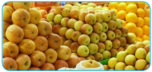
Let us consider the packing of fruits for display in fruit stalls. They are in a closest packed arrangement as shown in the following fig we can extend this analogy to visualize the packing of constituents (atoms/ions/ molecules) in crystals, by treating them as hard spheres.

To maximize the attractive forces between the constituents, they generally tend to pack together as close as possible to each other. In this portion we discuss how to pack identical spheres to create cubic and hexagonal unit cell. Before moving on to these three dimensional arrangements, let us first consider the two dimensional arrangement of spheres for better understanding.

Packing in Crystals img 1

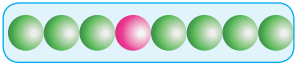
Linear Arrangement of Spheres in One Direction:

In a specific direction, there is only one possibility to arrange the spheres in one direction as shown in the fig. in this arrangement each sphere is in contact with two neighbouring spheres on either side.

Packing in Crystals img 2

Two Dimensional Close Packing:

Two dimensional planar packing can be done in the following two different ways.
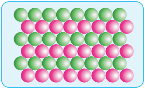
Packing in Crystals img 3

(i) AAA Type:

Linear arrangement of spheres in one direction is repeated in two dimension i.e., more number of rows can be generated identical to the one dimensional arrangement such that all spheres of different rows align vertically as well as horizontally as shown in the fig.

If we denote the first row as A type arrangement, then the above mentioned packing is called AAA type, because all rows are identical as the first one. In this arrangement each sphere is in contact with four of its neighbours.
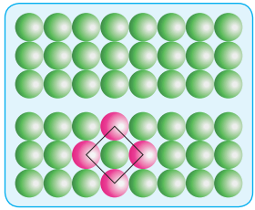
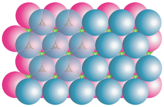
(ii) ABAB Type:

In this type, the second row spheres are arranged in such a way that they fit in the depression of the first row as shown in the figure. The second row is denoted as B type. The third row is arranged similar to the first row A, and the fourth one is arranged similar to second one. i.e., the pattern is repeated as ABAB.

In this arrangement each sphere is in contact with 6 of its neighbouring spheres. On comparing these two arrangements (AAAA…type and ABAB….type) we found that the closest arrangement is ABAB…type.

Packing in Crystals img 4

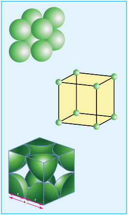
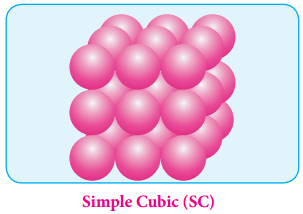
Simple Cubic Arrangement:

This type of three dimensional packing arrangements can be obtained by repeating the AAAA type two dimensional arrangements in three dimensions. i.e., spheres in one layer sitting directly on the top of those in the previous layer so that all layers are identical.

All spheres of different layers of crystal are perfectly aligned horizontally and also vertically, so that any unit cell of such arrangement as simple cubic structure as shown in fig. In simple cubic packing, each sphere is in contact with 6 neighbouring spheres Four in its own layer, one above and one below and hence the coordination number of the sphere in simple cubic arrangement is 6.

Packing in Crystals img 5

Packing Efficiency:

There is some free space between the spheres of a single layer and the spheres of successive layers. The percentage of total volume occupied by these constituent spheres gives the packing efficiency of an arrangement. Let us calculate the packing efficiency in simple cubic arrangement,

Packing in Crystals img 6

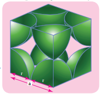
Let us consider a cube with an edge length ‘a’ as shown in fig. Volume of the cube with edge length a is = a × a × a = a3 Let ‘r’ is the radius of the sphere. From the figure, a = 2r ⇒r = \(\frac{a}{2}\)

∴ Volume of the sphere with radius ‘r’
= \(\frac{4}{3}\)πr3
= \(\frac{4}{3}\)π(\(\frac{a}{2}\))3
= \(\frac{4}{3}\)π(\(\frac{\mathrm{a}^{3}}{8}\))
= \(\frac{\pi \mathrm{a}^{3}}{6}\) ……………. (1)

In a simple cubic arrangement, number of spheres belongs to a unit cell is equal to one
∴ Total volume occupied by the spheres in sc unit cell = 1 × (\(\frac{\mathrm{a}^{3}}{6}\)) ……………… (2)
Dividing (2) by (3)
Packing Fraction = \(\frac{\left(\frac{\pi a^{3}}{6}\right)}{\left(a^{3}\right)}\) × 100 = \(\frac{100π}{6}\)
= 52.38%

i.e., only 52.38% of the available volume is occupied by the spheres in simple cubic packing, making inefficient use of available space and hence minimizing the attractive forces.

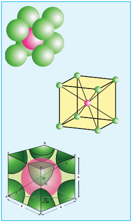
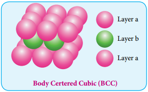
Body Centered Cubic Arrangement

In this arrangement, the spheres in the first layer (A type) are slightly separated and the second layer is formed by arranging the spheres in the depressions between the spheres in layer A as shown in figure. The third layer is a repeat of the first. This pattern ABABAB is repeated throughout the crystal. In this arrangement, each sphere has a coordination number of 8, four neighbors in the layer above and four in the layer below.

Packing in Crystals img 7

Packing Efficiency:

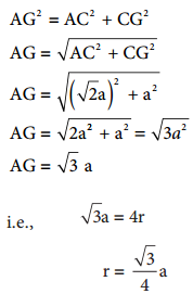
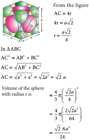
Here, the spheres are touching along the leading diagonal of the cube as shown in the fig.
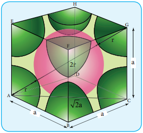
Packing in Crystals img 8

In ∆ABC
AC2 = AB2 + BC2
AC = \(\sqrt{\mathrm{AB}^{2}+\mathrm{BC}^{2}}\)
AC = \(\sqrt{\mathrm{a}^{2}+\mathrm{a}^{2}}\) = \(\sqrt{2 a^{2}}\) = \(\sqrt{2}\)a

In ∆ACG

Packing in Crystals img 9

∴ Volume of the sphere with radius ‘r’

Packing in Crystals img 10

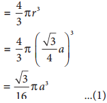
Number of spheres belong to a unit cell in bcc arrangement is equal to two and hence the total volume of all spheres

Packing in Crystals img 11

i.e., 68 % of the available volume is occupied. The available space is used more efficiently than in simple cubic packing.

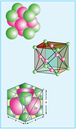
The Hexagonal and Face Centered Cubic Arrangement:

Formation of First Layer:

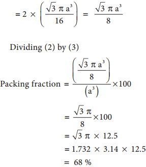
In this arrangement, the first layer is formed by arranging the spheres as in the case of two dimensional ABAB arrangements i.e. the spheres of second row fit into the depression of first row. Now designate this first layer as ‘a’. The next layer is formed by placing the spheres in the depressions of the first layer. Let the second layer be ‘b’.

Packing in Crystals img 12

Formation of Second Layer:

In the first layer (a) there are two types of voids (or holes) and they are designated as x and y. The second layer (b) can be formed by placing the spheres either on the depression (voids/holes) x (or) on y let us consider the formation of second layer by placing the spheres on the depression (x).

Wherever a sphere of second layer (b) is above the void (x) of the first layer (a), a tetrahedral void is formed. This constitutes four spheres – three in the lower (a) and one in the upper layer (b). When the centers of these four spheres are joined, a tetrahedron is formed.

At the same time, the voids (y) in the first layer (a) are partially covered by the spheres of layer (b), now such a void in (a) is called a octahedral void. This constitutes six spheres – three in the lower layer (a) and three in the upper layer (b).

When the centers of these six spheres are joined, an octahedron is formed. Simultaneously new tetrahedral voids (or holes) are also created by three spheres in second layer (b) and one sphere of first layer (a).

Packing in Crystals img 13

Formation of Third Layer:

The third layer of spheres can be formed in two ways to acheive closest packing

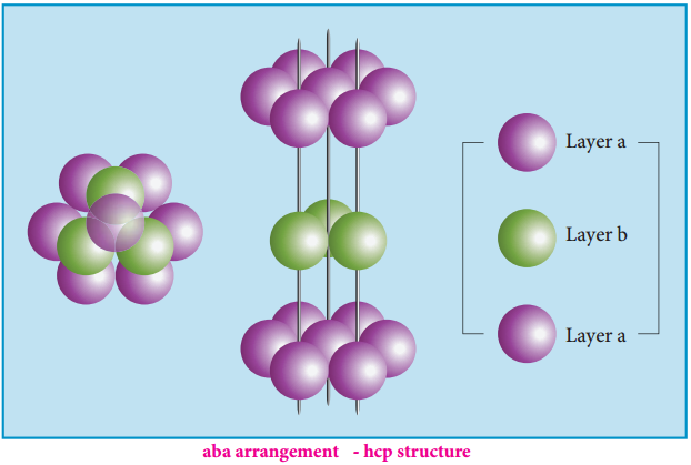
  • Aba arrangement – hcp structure
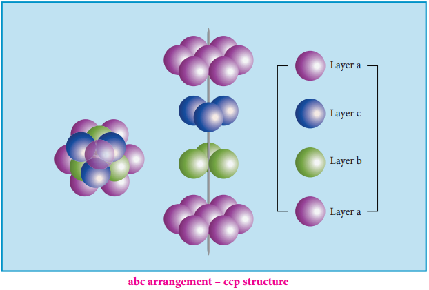
  • Abc arrangement – ccp structure

The spheres can be arranged so as to fit into the depression in such a way that the third layer is directly over a first layer as shown in the figure. This “aba’’ arrangement is known as the hexagonal close packed (hcp) arrangement. In this arrangement, the tetrahedral voids of the second layer are covered by the spheres of the third layer.

Alternatively, the third layer may be placed over the second layer in such a way that all the spheres of the third layer fit in octahedral voids. This arrangement of the third layer is different from other two layers (a) and (b), and hence, the third layer is designated (c). If the stacking of layers is continued in abcabcabc pattern, then the arrangement is called cubic close packed (ccp) structure.

In both hcp and ccp arrangements, the coordination number of each sphere is 12 – six neighbouring spheres in its own layer, three spheres in the layer above and three sphere in the layer below. This is the most efficient packing.

Packing in Crystals img 14

The cubic close packing is based on the face centered cubic unit cell. Let us calculate the packing efficiency in fcc unit cell.

Packing in Crystals img 15

Total number of spheres belongs to a single fcc unit cell is 4
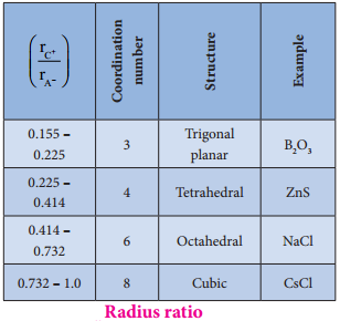
Packing in Crystals img 16

Radius Ratio:

The structure of an ionic compound depends upon the stoichiometry and the size of the ions.generally in ionic crystals the bigger anions are present in the close packed arrangements and the cations occupy the voids.

The ratio of radius of cation and anion (\(\frac{\mathrm{r}_{\mathrm{C}^{+}} {\mathrm{r}_{\mathrm{A}^{-}}}\)) plays an important role in determining the structure. The following table shows the relation between the radius ratio and the structural arrangement in ionic solids.

Packing in Crystals img 17

Primitive and Non-Primitive Unit Cell

Find free online Chemistry Topics covering a broad range of concepts from research institutes around the world.

Primitive and Non-Primitive Unit Cell

There are two types of unit cells:

There are two types of unit cells primitive and non-primitive. A unit cell that contains only one type of lattice point is called a primitive unit cell, which is made up from the lattice points at each of the corners. In case of non-primitive unit cells, there are additional lattice points, either on a face of the unit cell or with in the unit cell.

Primitive and Non-Primitive Unit Cell img 1

There are seven primitive crystal systems; cubic, tetragonal, orthorhombic, hexagonal, monoclinic, triclinic and rhombohedral. They differ in the arrangement of their crystallographic axes and angles. Corresponding to the above seven, Bravis defined 14 possible crystal systems as shown in the figure.

Primitive and Non-Primitive Unit Cell img 2

Primitive and Non-Primitive Unit Cell img 3
Primitive and Non-Primitive Unit Cell img 4

Number of atoms in a cubic cell:

Primitive (or) Simple Cubic Unit Cell(SC)

Primitive and Non-Primitive Unit Cell img 5

In the simple cubic unit cell, each corner is occupied by an identical atoms or ions or molecules. And they touch along the edges of the cube, do not touch diagonally. The coordination number of each atom is 6. Each atom in the corner of the cubic unit cell is shared by 8 neighboring unit cells and therefore atoms per unit cell is equal to \(\frac{\mathrm{N}_{\mathrm{c}}}{8}\), where Nc is the number of atoms at the corners.
∴ Number of atoms in a SC unit cell = (\(\frac{Nc}{8}\))
= (\(\frac{8}{8}\)) = 1

Body Centered Cubic Unit Cell(BCC)

Primitive and Non-Primitive Unit Cell img 6

In a body centered cubic unit cell, each corner is occupied by an identical particle and in addition to that one atom occupies the body centre. Those atoms which occupy the corners do not touch each other, however they all touch the one that occupies the body centre.

Hence, each atom is surrounded by eight nearest neighbours and coordination number is 8. An atom present at the body centre belongs to only to a particular unit cell i.e unshared by other unit cell.
∴ Number of atoms in a bcc unit cell = (\(\frac{Nc}{8}\)) + (\(\frac{\mathrm{N}_{\mathrm{b}}}{1}\))
= (\(\frac{8}{8}\) + \(\frac{1}{1}\))
= (1 + 1)
= 2

Face Centered Cubic Unit Cell(FCC)

Primitive and Non-Primitive Unit Cell img 7

In a face centered cubic unit cell, identical atoms lie at each corner as well as in the centre of each face. Those atoms in the corners touch those in the faces but not each other. The atoms in the face centre is being shared by two unit cells, each atom in the face centers makes (\(\frac{1}{2}\)) contribution to the unit cell.
∴ Number of atoms in a fcc unitcell = (\(\frac{\mathrm{N}_{\mathrm{c}}}{8}\)) + (\(\frac{\mathrm{N}_{\mathrm{f}}}{8}\))
= (\(\frac{8}{8}\) + \(\frac{6}{2}\))
= (1 + 3)
= 4

Drawing the crystal lattice on paper is not an easy task. The constituents in a unit cell touch each other and form a three dimensional network. This can be simplified by drawing crystal structure with the help of small circles (spheres) corresponding constituent particles and connecting neighbouring particles using a straight line as shown in the figure.

Calculations Involving Unit Cell Dimensions:

X-Ray diffraction analysis is the most powerful tool for the determination of crystal structure. The inter planar distance (d) between two successive planes of atoms can be calculated using the following equation form the X-Ray diffraction data 2dsinθ = nλ

The above equation is known as Bragg’s equation.

Where

λ is the wavelength of X-ray used for diffraction.
θ is the angle of diffraction
n is the order of diffraction

By knowing the values of θ, λ and n we can calculate the value of d.

d = \(\frac{nλ}{2sinθ}\)

Using these values the edge length of the unit cell can be calculated.

Calculation of Density:

Using the edge length of a unit cell, we can calculate the density (ρ) of the crystal by considering a cubic unit cell as follows.

Primitive and Non-Primitive Unit Cell img 8

Equation (6) contains four variables namely ρ, n, M and a. If any three variables are known, the fourth one can be caluculated.