Adsorption and Absorption

Find free online Chemistry Topics covering a broad range of concepts from research institutes around the world.

Adsorption and Absorption

Solid surfaces have the ability to attract the contacting species due to free valency or residual force on them.

For example:
charcoal adsorbs ammonia, silica gel adsorbs water., charcoal adsorbs colorants from sugar.

These examples prove that adsorption is a surface phenomenon. In contrast to adsorption, absorption is a bulk phenomenon i.e. the adsorbate molecules are distributed throughout the adsorbent.

  1. Adsorbent is the material on which adsorption takes place.
  2. Adsorbed substance is called an adsorbate.
  3. The surface of separation of the two phases where the concentration of adsorbed molecule is high is known as interface.
  4. In adsorption, if the concentration of a substance in the interface is high, then it is called positive adsorption.
  5. If it is less, then it is called negative adsorption.
  6. The process of removing an adsorbed substance from the surface is called desorption.
  7. The gaseous molecules like He, Ne, O2, SO2 and NH3 and solutions of NaCl or KCl can be adsorbed by suitable adsorbents. These are referred as adsorbates.
  8. Silica gel and metals like Ni, Cu, Pt, Ag and Pd and certain colloids can act as adsorbents.

Characteristics of Adsorption

1. Adsorption can occur in all interfacial surfaces i.e. the adsorption can occur in between gas-solid, liquid solid, liquid-liquid, solid-solid and gas-liquid.

2. Adsorption is a spontaneous process and it is always accompanied by decrease in free energy. When ∆G reaches zero, the equilibrium is attained. We know,

∆G = ∆H – T ∆S where ∆G is Change in Free energy.
∆H is Change in enthalpy and ∆S = Change in entropy.

3. When molecules are adsorbed, there is always a decrease in randomness of the molecules. ie., ∆S < 0, and T∆S is negative. Hence, adsorption is exothermic. Adsorption is a quick process whereas absorption is a slow process.

Types of Adsorption

Adsorption is classifid as physical adsorption and chemical adsorption, depending on the nature of forces acting between adsorbent and adsorbate. In chemical adsorption, gas molecules are held to the surface by formation of chemical bonds. Since strong bond is formed, nearly 400 KJ / mole is given out as heat of adsorption.

Examples

(a) Adsorption of O2 on tungsten, Adsorption of H2 on nickel, Adsorption of ethyl alcohol vapours on nickel.

In physical adsorption, physical forces such as van der waals force of attraction, dipole – dipole interaction, dispersion forces etc., exist between adsorbent and adsorbate. As these forces are weak, heat of adsorption is low, hence physical adsorption occurs at low temperatures.

Examples

(a) Adsorption of N2 on mica.
(b) Adsorption of gases on charcoal.

The following table 10.1 illustrates the distinction between chemical and physical adsorption.

Distinction Between Chemical and Physical Adsorption

Chemical adsorption or Chemisorption or Activated adsorptionPhysical adsorption or van der waals
adsorption or Physisorption
1. It is very slow1. It is instantaneous
2. It is very specific depends on nature of
adsorbent and adsorbate.
2. It is non-specific
3. Chemical adsorption is fast with increase pressure, it can not alter the amount3. In Physisorption, when pressure increases the extent of adsorption increases
4. When temperature is raised chemisorption first increases and then
decreases
4. Physisorption decreases with increase in
temperature
5. Chemisorption involves transfer of electrons between the adsorbent and adsorbate5. No transfer of electrons
6. Heat of adsorption is high i.e., from 40-
400kJ/mole
6. Heat of adsorption is low in the order of
40kJ/mole.
7. Monolayer of the adsorbate is formed7. Multilayer of the adsorbate is formed on
the adsorbent
8. Adsorption occurs at fixed sites called
active centres. It depends on surface area
8. It occurs on all sides
9. Chemisorption involves the formation
of activated complex with appreciable
activation energy
9. Activation energy is insignifiant

Factors Affecting Adsorption

The adsorption is well understood by considering the various factors affecting it. Qualitatively, the extent of surface adsorption depends on the following factors.

  1. Nature of adsorbent
  2. Nature of adsorbate
  3. Pressure
  4. Concentration at a given temperature.

1. Surface Area of Adsorbent:

As the adsorption is a surface phenomenon it depends on the surface area of adsorbent. i.e., higher the surface area, higher is the amount adsorbed.

2. Nature of Adsorbate

The nature of adsorbate can inflence the adsorption. Gases like SO2, NH3, HCl and CO2 are easily liquefiable as they have greater van der waal’s force of attraction. On the other hand, permanent gases like H2, N2 and O2 can not be liquefied easily. These permanent gases are having low critical temperature and adsorbed slowly, while gases with high critical temperature are adsorbed readily.

3. Effect of Temperature

When temperature is raised chemisorption fist increases and then decreases. whereas physisorption decreases with increase in temperature.

4. Effect of Pressure:

chemical adsorption is fast with increase in pressure, it can not alter the amount of adsorption. In Physisorption the extent of adsorption increases with increase in pressure.

Adsorption Isotherms and Isobars

Adsorption isotherms represents the variation of adsorption at constant temperature. When amount of adsorption is plotted versus temperature at constant pressure it is called adsorption isobar. Adsorption isobars of physisorption and chemisorption are different as represented in the graphs.

Adsorption and Absorption img 1

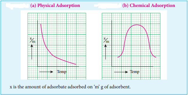
In physical adsorption, \(\frac{x}{m}\) decreases with increase in Temprature, But in chemical adsorption, \(\frac{x}{m}\) increases with rise in temperature and then decreases.

The increase illustrates the requirement of activation of the surface for adsorption is due to fact that formation of activated complex requires certain energy. The decrease at high temperature is due to desorption, as the kinetic energy of the adsorbate increases.

Adsorption Isotherms

Adsorption isotherm can be studied quantitatively. A plot between the amount of adsorbate adsorbed and pressure (or concentration of adsorbate) at constant temperature is called adsorption isotherms. In order to explain these isotherms various equations were suggested as follows:

(i) Freundlich adsorption isotherm.
According to Freundlich,
\(\frac{x}{m}\) = kp1/n

where x is the amount of adsorbate, adsorbed on ‘m’ gm of adsorbent at a pressure of p. K and n are constant introduced by freundlich. Value n is always less than unity.

This equation is applicable for adsorption of gases on solid surfaces. The same equation becomes \(\frac{x}{m}\) = K c1/n, when used for adsorption in solutions with c as concentration.

This equation quantitively predicts the effect of pressure(or concentration) on the adsorption of gases(or adsorbates) at constant temperature.

Taking log on both sides of equation \(\frac{x}{m}\) = Kp1/n
log \(\frac{x}{m}\) = logK + \(\frac{1}{n}\)log P

Adsorption and Absorption img 2

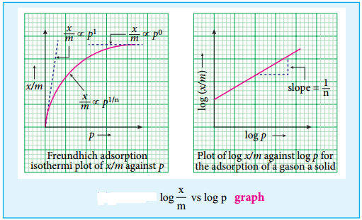
Hence the intercept represents the value of log k and the slope gives \(\frac{1}{n}\).

This equation explains the increase of \(\frac{x}{m}\) with increase in pressure. But experimental values show the deviation at low pressure.

Limitations

This equation is purely empirical and valid over a limited pressure range. The values of constants k and n also found vary with temperature. No theoretical explanations were given.

Applications of Adsorption

Though we have innumerable applications for adsorption, we consider few of them

1. Gas Masks:

During world war I charcoal gas mask was employed by both the British and American. Activated charcoal was found to be one of the best adsorbents.

2. To create high vacuum in vessels, Tail and Dewar used activated charcoal. For dehydration and also purification of gases like CO2, N2, Cl2, O2 and He, alumina and silica are employed. In the blast furnace silica gel is also used for drying air.

3. One of the highly important use of adsorption is the softening of hardwater. Permutit is employed for this process which adsorbs Ca2+ and Mg2+ ions in its surface, there is an ion exchange as shown below it occurs on the surface.

Na2Al2Si4O12 + CaCl2 → CaAl2Si4O12 + 2NaCl

Exhausted permutit is regenerated by adding a solution of common salt.

CaAl2Si4O12 + 2NaCl → Na2Al2Si4O12 + CaCl2

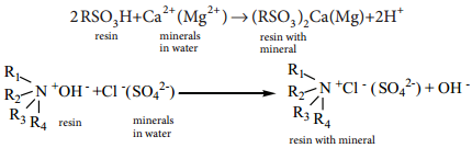
4. Ion Exchange Resins

Ion exchange resins are working only based on the process of adsorption. Ion exchange resins are used to demineralise water. This process is carried out by passing water through two columns of cation and anion exchange resins.

Adsorption and Absorption img 3

5. Petroleum Refining and Refining of Vegetable Oil

Fuller’s earth and silica gel are used for refining process.

6. Decolourisation of Sugar:

Sugar prepared from molasses is decolourised to remove coloured impurities by adding animal charcoal which acts as decolourising material.

7. Chromatography

The chromatographic technique is applied for separation of components in a mixture. It is mainly based on adsorption of components on the surface of adsorbents. This method is very effective and used for identification, detection and estimation of many substances even if they are contained in micro quantities.

8. Catalysed Reaction

Catalysis is an important branch of surface chemistry which is based on the phenomenon of adsorption of materials on the catalyst surface.

Examples:

In the Haber’s process, ammonia is manufactured from N2 and H2 as shown by the following reactions.

In this process, Fe is the catalyst and Mo is a promoter. The surface of the Fe catalyses the reaction.

In the hydrogenation of oils to obtain vanaspathi, Nickel is used as a catalyst. Nickel surface catalyses the reaction.

Adsorption and Absorption img 4

9. Qualitative Analysis

When blue litmus solution is added to Al3+ ion, a red coloration is seen due to the acidic nature of the solution. Addition of ammonium hydroxide to it gives a blue lake. This is due to the adsorption of blue colour litmus compound on the surface of Al (OH)3 Which is formed during the addition of NH4OH.

10. Medicine:

Drugs cure diseases by adsorption on body tissues.

11. Concentration of Ores of Metals

Sulphides ores are concentrated by a process called froth fltation in which light ore particles are wetted by pine oil.

12. Mordants and Dyes

Most of the dyes are adsorbed on the surface of the fabrics. Mordants are the substances used for fining dyes onto the fabric.

13. Adsorption Indicators

In the precipitation titrations, the end point is indicated by an external indicator which changes its colour after getting adsorbed on precipitate. It is used to indicate the end point of the titration.

Thermodynamics of Cell Reactions

Find free online Chemistry Topics covering a broad range of concepts from research institutes around the world.

Thermodynamics of Cell Reactions

We have just learnt that in a galvanic cell, the chemical energy is converted into electrical energy. The electrical energy produced by the cell is equal to the product of the total charge of electrons and the emf of the cell which drives these electrons between the electrodes.

If ‘n’ is the number of moles of electrons exchanged between the oxidising and reducing agent in the overall cell reaction, then the electrical energy produced by the cell is given as below.

Electrical energy = Charge of ‘n’ mole of electrons × Ecell ……. (9.20)
Charge of 1 mole of electrons = one Faraday (1F)
∴ Charge of ‘n’ mole of electrons = nF
Equation (9.20) ⇒ Electrical energy = nFEcell ……. (9.21)

∴ Charge of one elctron = 1.602 × 10⁻¹⁹C
∴ Charge of one mole of elctron = 6.023 × 1023 × 1.602 × 10-19C
= 96488 C
i.e., 1F = 96500 C

This energy is used to do the electric work. Therefore the maximum work that can be obtained from a galvanic cell is

(Wmax)cell = – nFEcell …………… (9.22)

Here the (-) sign is introduced to indicate that the work is done by the system on the surroundings.

We know from the Second Law of thermodynamics that the maximum work done by the system is equal to the change in the Gibbs free energy of the system.

i.e., Wmax = ∆G …………… (9.23)

From (9.22) and (9.23),

∆G = – nFEcell ……………. (9.24)

For a spontaneous cell reaction, the DG should be negative. The above expression (9.24) indicates that Ecell should be positive to get a negative ∆G value.

When all the cell components are in their standard state, the equation (9.24) becomes

∆G° = – nFE°cell ………….. (9.25)

We know that the standard free energy change is related to the equilibrium constant as per the following expression.

∆G° = – RTlnKeq …………… (9.26)
Comparing (9.25) and (9.26),
⇒ E°cell = \(\frac{2.303RT}{nF}\)log Keq ………….. (9.27)

Nernst Equation

Nernst equation is the one which relates the cell potential and the concentration of the species involved in an electrochemical reaction. Let us consider an electrochemical cell for which the overall redox reaction is,
xA + yB ⇄ lC + mD. The reaction quotient Q for the above reaction is given below

Thermodynamics of Cell Reactions img 1 ……….. (9.28)

We have already learnt that,
∆G = ∆G° + RT lnQ

The Gibbs free energy can be related to the cell emf as follows [∴equation (9.24) and (9.25)]
∆G = – nFE cell; ∆G° = – nFE°cell
Substitute these values and Q from (9.28) in the equation (9.29)

Thermodynamics of Cell Reactions img 2 ………… (9.30)

Divide the whole equation (9.30) by (-nF)

Thermodynamics of Cell Reactions img 3 ………… (9.31)

The above equation (9.31) is called the Nernst equation. At 25°C (298K), the above equation (9.31) becomes,

Thermodynamics of Cell Reactions img 4 ……………… (9.32)

Let us calculate the emf of the following cell at 25°C using Nernst equation

Cu (s)|Cu2+(0.25 aq, M)|Fe2+(0.1 aq M)|Pt(s)
Given: (E°)Fe2+|Fe2+ = 0.77V and (E°)Cu2+|Cu = 0.34 V

Half reactions are
Cu (s) → Cu2+(aq) + 2e …………… (1)
2 Fe3+(aq) + 2e → 2Fe2+(aq) …………. (2)

the overall reaction is

Cu (s) + 2Fe3+(aq) → Cu2+(aq) + 2Fe2+ (aq), and n = 2
Apply Nernst equation at 25°C.

Thermodynamics of Cell Reactions img 5

Given standard reduction potential of Cu2+|Cu is 0.34V

Thermodynamics of Cell Reactions img 6

Electrolytic Cell and Electrolysis

Electrolysis is a process in which the electrical energy is used to cause a non-spontaneous chemical reaction to occur; the energy is often used to decompose a compound into its elements. The device which is used to carry out the electrolysis is called the electrolytic cell.

The electrochemical process occurring in the electrolytic cell and galvanic cell are the reverse of each other. Let us understand the function of a electrolytic cell by considering the electrolysis of molten sodium chloride.

The electrolytic cell consists of two iron electrodes dipped in molten sodium chloride and they are connected to an external DC power supply via a key as shown in the figure (9.8). The electrode which is attached to the negative end of the power supply is called the cathode, and the one which attached to the positive end is called the anode. Once the key is closed, the external DC power supply drives the electrons to the cathode and at the same time pull the electrons from the anode.

Thermodynamics of Cell Reactions img 7

Cell Reactions

Na+ ions are attracted towards cathode, where they combine with the electrons and reduced to liquid sodium.

Cathode (Reduction)

Na+(l) + e → Na(l) E° = – 2.71
Similarly, Cl ions are attracted towards anode where they lose their electrons and oxidised to chlorine gas.

Anode (Oxidation)

2Cl(l) → Cl2(g) + 2e E° = – 1.36V

The overall reaction is,
2Na+(l) + 2Cl(l) → 2Na(l) + Cl2(g) E° = – 4.07V

The negative E° value shows that the above reaction is a non spontaneous one. Hence, we have to supply a voltage greater than 4.07V to cause the electrolysis of molten NaCl. In electrolytic cell, oxidation occurs at the anode and reduction occur at the cathode as in a galvanic cell, but the sign of the electrodes is the reverse i.e., in the electrolytic cell cathode is – ve and anode is + ve.

Faraday’s Laws of Electrolysis
First Law

The mass of the substance (m) liberated at an electrode during electrolysis is directly proportional to the quantity of charge (Q) passed through the cell.

i.e m α Q

We know that the charge is related to the current by the equation I = \(\frac{Q}{t}\) ⇒ Q = It
∴ m α It
(or)
m = Z It …………. (9.33)

Where is Z is known as the electro chemical equivalent of the substance produced of the electrode. When, I = 1A and t = 1sec, Q = 1C, in such case the equation (9.32) becomes, (9.33)
⇒ m = Z …………….. (9.34)

Thus, the electrochemical equivalent is defined as the amount of substance deposited or liberated at the electrode by a charge of 1 coulomb.

Electro Chemical Equivalent and Molar Mass

Consider the following general electrochemical redox reaction
Mn+(aq) + ne → M(s)
We can infer from the above equation that ‘n’ moles of electrons are required to precipitate 1 mole of Mn+ as M(s).

The quantity of charge required to precipitate one mole of Mn+ = Charge of ‘n’ moles of electrons
= nF

In other words, the mass of substance deposited by one coulomb of charge

Thermodynamics of Cell Reactions img 8 …………… (9.35)

Second Law

Thermodynamics of Cell Reactions img 9

When the same quantity of charge is passed through the solutions of different electrolytes, the amount of substances liberated at the respective electrodes are directly proportional to their electrochemical equivalents.

Let us consider three electrolytic cells connected in series to the same DC electrical source as shown in the figure 9.9. Each cell is filled with a different electrolytes namely NiSO4, CuSO4 and CoSO4, respectively.

When Q coulomb charge is passed through the electrolytic cells the masses of Nickel, copper and cobalt deposited at the respective electrodes be mNi, mCu and mCo, respectively.

According to Faraday’s second Law,

Thermodynamics of Cell Reactions img 10 ………….. (9.36)

Batteries

Batteries are indispensable in the modern electronic world. For example, Li – ion batteries are used in cell phones, dry cell in flashlight etc. These batteries are used as a source of direct current at a constant voltage. We can classify them into primary batteries (non – rechargeable) and secondary batteries (rechargeable). In this section, we will briefly discuss the electrochemistry of some batteries.

Leclanche Cell

Anode: Zinc container
Cathode: Graphite rod in contact with MnO2
Electrolyte: ammonium chloride and zinc chloride in water

Emf of the cell is about 1.5V
Cell reaction

Oxidation at Anode
Zn (s) → Zn2+(aq) + 2e ……… (1)

Reduction at Cathode
2 NH4+(aq) + 2e → 2NH3(aq) + H2(g) ………… (2)

The hydrogen gas is oxidised to water by MnO2
H2 (g) + 2 MnO2 (s) → Mn2O3(s) + H2O(l)
Equation (1) + (2)+(3) gives the overall redox reaction

Thermodynamics of Cell Reactions img 11

Zn (s) + 2NH4+(aq) + 2 MnO2(s) → Zn2+(aq) + Mn2O3 (s) + H2O(l) + 2NH3 ………… (4)

Ammonia produced at the cathode combines with Zn2+ to form a complex ion [Zn(NH3)4]2+(aq). As the reaction proceeds, the concentration of NH4+ will decrease and the aqueous NH3 will increase which lead to the decrease in the emf of cell.

Mercury Button Cell

Anode: zinc amalgamated with mercury
Cathode: HgO mixed with graphite
Electrolyte: Paste of KOH and ZnO

Thermodynamics of Cell Reactions img 18

Overall reaction: Zn (s) + HgO (s) → ZnO (s) + Hg (l)
Cell emf: about 1.35V.
Uses: It has higher capacity and longer life. Used in pacemakers, electronic watches, cameras etc.

Thermodynamics of Cell Reactions img 12

Secondary Batteries

We have already learnt that the electrochemical reactions which take place in a galvanic cell may be reversed by applying a potential slightly greater than the emf generated by the cell. This principle is used in secondary batteries to regenerate the original reactants. Let us understand the function of secondary cell by considering the lead storage battery as an example.

Lead Storage Battery

Anode: Spongy lead
Cathode: lead plate bearing PbO2
Electrolyte: 38% by mass of H2SO4 with density 1.2g / mL.

Oxidation occurs at the anode

Pb(s) → Pb2+(aq) + 2e ……….. (1)
The Pb2+ ions combine with SO42-(aq) → PbSO4 (s) …………. (2)

Reduction occurs at the cathode

PbO2 (s) + 4 H+(aq) + 2e → Pb2+(aq) + 2H2O(l) ………. (3)
The Pb2+ ions also combine with SO42- → Pb2+(aq) + 2H2O(l)

The emf of a single cell is about 2V. Usually six such cells are combined in series to produce 12 volt

The emf of the cell depends on the concentration of H2SO4. As the cell reaction uses SO42-
ions, the concentration H2SO4 decreases. When the cell potential falls to about 1.8V, the cell has to be recharged.

Recharge of the Cell

As said earlier, a potential greater than 2V is applied across the electrodes, the cell reactions that take place during the discharge process are reversed. During recharge process, the role of anode and cathode is reversed and H2SO4 is regenerated.

Oxidation occurs at the cathode (now act as anode)

image

Reduction occurs at the anode (now act as cathode) PbSO4(s) + 2e → Pb(s) + SO42-(aq)
Overall reaction
2PbSO4(s) + 2H2O(l) → Pb(s) + PbO2(s) + 4H+(aq) + 2SO42-(aq)

Thus, the overall cell reaction is exactly the reverse of the redox reaction which takes place while discharging.

Uses:
Used in automobiles, trains, inverters etc.

The lithium – ion Battery

Anode: Porus graphite
Cathode: Transition metal oxide such as CoO2.

Thermodynamics of Cell Reactions img 13

Electrolyte: Lithium salt in an organic solvent
At the anode oxidation occurs
Li (s) → Li+(aq) + e

At the cathode reduction occurs
Li+ + CoO2(s) + e → LiCoO2(s)

Overall reactions
Li (s) + CoO2 → LiCoO2 (s)

Both electrodes allow Li+ ions to move in and out of their structures.

During discharge, the Li+ ions produced at the anode move towards cathode through the non – aqueous electrolyte. When a potential greater than the emf produced by the cell is applied across the electrode, the cell reaction is reversed and now the Li+ ions move from cathode to anode where they become embedded on the porous graphite electrode. This is known as intercalation.

Thermodynamics of Cell Reactions img 14

Uses:

Used in cellular phones, laptops, computers, digital cameras, etc.

Fuel Cell:

The galvanic cell in which the energy of combustion of fuels is directly converted into electrical energy is called the fuel cell. It requires a continuous supply of reactant to keep functioning. The general representation of a fuel cell is follows.

Thermodynamics of Cell Reactions img 15

Fuel | Electrode | Electrolyte | Electrode | Oxidant

Let us understand the function of fuel cell by considering hydrogen – oxygen fuel cell. In this case, hydrogen act as a fuel and oxygen as an oxidant and the electrolyte is aqueous KOH maintained at 200°C and 20 – 40 atm. Porous graphite electrode containing Ni and NiO serves as the inert electrodes.

Hydrogen and oxygen gases are bubbled through the anode and cathode, respectively.

Oxidation occurs at the anode:
2H2g + 4 OH(aq) → 4H2O(l) + 4e
Reduction occurs at the cathode O2(g) + 2H2O(l) + 4e → 4 OH(aq)

The overall reaction is 2H2 (g) + O2 (g) → 2H2O(l)

The above reaction is the same as the hydrogen combustion reaction, however, they do not react directly ie., the oxidation and reduction reactions take place separately at the anode and cathode respectively like H2 – O2 fuel cell. Other fuel cells like propane – O2 and methane O2 have also been developed.

Corrosion

We are familiar with the rusting of iron. Have you ever noticed a green film formed on copper and brass vessels?. In both, the metal is oxidised by oxygen in presence of moisture. This redox process which causes the deterioration of metal is called corrosion.

As the corrosion of iron causes damages to our buildings, bridges etc… it is important to know the chemistry of rusting and how to prevent it. Rusting of iron is an electrochemical process.

Electrochemical Mechanism of Corrosion

The formation of rust requires both oxygen and water. Since it is an electrochemical redox process, it requires an anode and cathode in different places on the surface of iron. The iron surface and a droplet of water on the surface as shown in figure (9.15) form a tiny galvanic cell. The region enclosed by water is exposed to low amount of oxygen and it acts as the anode.

The remaining area has high amount of oxygen and it acts as cathode. So based on the oxygen content, an electro chemical cell is formed corrosion occurs at the anode i,e,. in the region enclosed by the water as discussed below.

Thermodynamics of Cell Reactions img 16

At Anode (Oxidation):

Iron dissolves in the anode region

2Fe (s) → 2Fe2+ (aq) + 4e E° = 1.23V

The electrons move through the iron metal from the anode to the cathode area where the oxygen dissolved in water, is reduced to water.

At Cathode (Reduction):

The reaction of atmospheric carbon dioxide with water gives carbonic acid which furnishes the H+ ions for reduction.

O2(g) + 4H+(aq) + 4e → 2H2O(l) E° = 0.44 + 1.23 = 1.67V

The positive emf value indicates that the reaction is spontaneous.

Fe2+(aq) + O2(g) + 4H+(aq) → 4Fe3+(aq) + 2H2O(l)
4Fe3+(aq) + 4H2O(l) → Fe2O3.H2O(s) + 6H+(aq)

Other metals such as aluminium, copper and silver also undergo corrosion, but at a slower rate than iron. For example, let us consider the reduction of aluminium,
Al(s) → Al3+(aq) + 3e

Al3+, which reacts with oxygen in air to forms a protective coating of Al2O3. This coating act as a protective film for the inner surface. So, further corrosion is prevented.

Protection of Metals form Corrosion

This can be achieved by the following methods.

  • Coating metal surface by paint.
  • Galvanizing – by coating with another metal such as zinc. zinc is stronger reducing agent than iron and hence it can be more easily corroded than iron. i.e., instead of iron, the zinc is oxidised.
  • Cathodic protection – In this technique, unlike galvanising the entire surface of the metal to be protected need not be covered with a protecting metal.

Instead, metals such as Mg or zinc which is corroded more easily than iron can be used as a sacrificial anode and the iron material acts as a cathode. So iron is protected, but Mg or Zn is corroded.

Passivation:

The metal is treated with strong oxidising agents such as concentrated HNO3. As a result, a protective oxide layer is formed on the surface of metal.

Alloy Formation:

The oxidising tendency of iron can be reduced by forming its alloy with other more anodic metals.
Example, stainless steel – an alloy of Fe and Cr.

Electrochemical Series

We have already learnt that the standard single electrode potentials are measured using standard hydrogen electrode. The standard electrode potential at 298K for various metal metal ion electrodes are arranged in the decreasing order of their standard reduction potential values as shown in the figure. This series is called electrochemical series.

The standard reduction potential (E°) is a measure of the oxidising tendency of the species. The greater the E° value, greater is the tendency shown by the species to accept electrons and undergo reduction. So higher the (E°) Value, lesser is the tendency to undergo corrosion.

Thermodynamics of Cell Reactions img 17

Electrochemical Cell

Find free online Chemistry Topics covering a broad range of concepts from research institutes around the world.

Electrochemical Cell

Electrochemical cell is a device which converts chemical energy into electrical energy and vice versa. It consists of two separate electrodes which are in contact with an electrolyte solution. Electrochemical cells are mainly classified into the following two types.

1. Galvanic Cell (Voltaic Cell):

It is a device in which a spontaneous chemical reaction generates an electric current i.e., it converts chemical energy into electrical energy. It is commonly known as a battery.

2. Electrolytic Cell:

It is a device in which an electric current from an external source drives a nonspontaneous reaction i.e., it converts electrical energy into chemical energy.

Galvanic Cell

We have already learnt in XI standard that when a zinc metal strip is placed in a copper sulphate solution, the blue colour of the solution fades and the copper is deposited on the zinc strip as red – brown crust due to the following spontaneous chemical reaction.

Zn(s) + CuSO4(aq) → ZnSO4(aq) + Cu(s)

The energy produced in the above reaction is lost to the surroundings as heat.

In the above redox reaction, Zinc is oxidised to Zn2+ ions and the Cu2+ ions are reduced to metallic copper.
The half reactions are represented as below.

Zn(s) → Zn2+(aq) + 2e (oxidation)
Cu2+(aq) + 2e → Cu(s) (reduction)

If we perform the above two half reactions separately in an apparatus as shown in figure 9.5, some of the energy produced in the reaction will be converted into electrical energy. Let us understand the function of a galvanic cell by considering Daniel cell as an example. It uses the above reaction for generation of electrical energy. The separation of half reaction is the basis for the construction of Daniel cell. It consists of two half cells.

Oxidation Half Cell

A metallic zinc strip that dips into an aqueous solution of zinc sulphate taken in a beaker, as shown in Figure 9.5.

Electrochemical Cell img 1

Reduction Half Cell

A copper strip that dips into an aqueous solution of copper sulphate taken in a beaker, as shown in Figure 9.5.

Electrochemical Cell img 2

Joining the Half Cells

The zinc and copper strips are externally connected using a wire through a switch (k) and a load (example: volt meter). The electrolytic solution present in the cathodic and anodic compartment are connected using an inverted U tube containing a agar-agar gel mixed with an inert electrolytes such as KCl, Na2SO4 etc., The ions of inert electrolyte do not react with other ions present in the half cells and they are not either oxidised (or) reduced at the electrodes. The solution in the salt bridge cannot get poured out, but through which the ions can move into (or) out of the half cells.

When the switch (k) closes the circuit, the electrons flows from zinc strip to copper strip. Ths is due to the following redox reactions which are taking place at the respective electrodes.

Anodic Oxidation

The electrode at which the oxidation occurs is called the anode. In Daniel cell, the oxidation take place at zinc electrode, i.e., zinc is oxidised to Zn2+ ions by loosing its electrons. The Zn2+ ions enter the solution and the electrons enter the zinc metal, then flow through the external wire and then enter the copper strip. Electrons are liberated at zinc electrode and hence it is negative (- ve).

Zn(s) → Zn2+(aq) + 2e (loss of electron-oxidation)

Cathodic Reduction

As discussed earlier, the electrons flow through the circuit from zinc to copper, where the Cu2+ ions in the solution accept the electrons, get reduced to copper and the same get deposited on the electrode. Here, the electrons are consumed and hence it is positive (+ ve).

Cu2+ + 2e → Cu (s) (gain of electron-reduction)

Salt Bridge

The electrolytes present in two half cells are connected using a salt bridge. We have learnt that the anodic oxidation of zinc electrodes results in the increase in concentration of Zn2+ in solution. i.e., the solution contains more number of Zn2+ ions as compared to SO42- and hence the solution in the anodic compartment would become positively charged.

Similarly, the solution in the cathodic compartment would become negatively charged as the Cu2+ ions are reduced to copper i.e., the cathodic solution contain more number of SO42- ions compared to Cu2+.

To maintain the electrical neutrality in both the compartments, the non reactive anions Cl (from KCl taken in the salt bridge) move from the salt bridge and enter into the anodic compartment, at the same time some of the K+ ions move from the salt bridge into the cathodic compartment.

Completion of Circuit

Electrons flow from the negatively charged zinc anode into the positively charged copper cathode through the external wire, at the same time, anions move towards anode and cations are move towards the cathode compartment. This completes the circuit.

Consumption of Electrodes

As the Daniel cell operates, the mass of zinc electrode gradually decreases while the mass of the copper electrode increases and hence the cell will function until the entire metallic zinc electrode is converted in to Zn2+ or the entire Cu2+ ions are converted in to metallic copper.

Unlike Daniel cell, in certain cases, the reactants (or) products cannot serve as electrodes and in such cases insert electrode such as graphite (or) platinum is used which conducts current in the external circuit.

Galvanic Cell Notation

The galvanic cell is represented by a cell diagram, for example, Daniel cell is represented as

Zn (s)|Zn2+(aq)||Cu2+(aq)|Cu (s)

In the above notation, a single vertical bar (|) represents a phase boundary and the double vertical bar (||) represents the salt bridge. The anode half cell is written on the left side of the salt bridge and the cathode half cell on the right side.

The anode and cathode are written on the extreme left and extreme right, respectively. The emf of the cell is written on the right side after cell diagram.

Electrochemical Cell img 3

Example

The net redox reaction of a galvanic cell is given below
2 Cr (s) + 3Cu2+(aq) → 2Cr3+ (aq) + 3Cu (s)

Write the half reactions and describe the cell using cell notation.
Anodic oxidation 2Cr (s) → 2Cr3+ (aq) + 6e ….. (1)
Cathodic reduction : 3Cu2+ (aq) + 6e → 3 Cu (s) ….. (2)

Cell Notation is
Cr (s)|Cr 3+(aq)||Cu2+(aq)|Cu(s)

Emf of a Cell

We have learnt that when two half cells of a Daniel cell are connected, a spontaneous redox reaction will take place which results in the flow of electrons from anode to cathode. The force that pushes the electrons away from the anode and pulls them towards cathode is called the electromotive force (emf) (or) the cell potential. The SI unit of cell potential is the volt (v).

When there is one volt difference in electrical potential between the anode and cathode, one joule of energy is released for each columb of charge that moves between them.

i.e., 1J = 1C × 1V ….. (9.18)

The cell voltage depends on the nature of the electrodes, the concentration of the electrolytes and the temperature at which the cell is operated. For example

At, 25°C , The emf of the below mentioned Daniel cell is 1.107 Volts

Zn (s)|Zn2+(aq, 1M)||Cu2+(aq, 1M)|Cu (s) E° = 1.107 V0lts

Measurement of Electrode Potential

The overall redox reaction can be considered as the sum of two half reactions i.e., oxidation and reduction. Similarly, the emf of a cell can be considered as the sum of the electrode potentials at the cathode and anode,

Ecell = (Eox)anode + (Ered)cathode ….. (9.19)

Here, (Eox)anode represents the oxidation potential at anode and (Ered)cathode represents the reduction potential at cathode. It is impossible to measure the emf of a single electrode, but we can measure the potential difference between the two electrodes (Ecell) using a voltmeter.

If we know the emf of any one of the electrodes which constitute the cell, we can calculate the emf of the other electrode from the measured emf of the cell using the expression (9.19). Hence, we need a reference
electrode whose emf is known.

For that purpose, Standard Hydrogen Electrode (SHE) is used as the reference electrode. It has been assigned an arbitrary emf of exactly zero volt. It consists of a platinum electrode in contact with 1M HCl solution and 1 atm hydrogen gas. The hydrogen gas is bubbled through the solution at 25°C as shown in the figure 9.6. SHE can act as a cathode as well as an anode.

The Half cell reactions are given below.

If SHE is used as a cathode, the reduction reaction is
2H+(aq, 1M) + 2e → H2(g, 1 atm) E° = 0 volt

If SHE is used as an anode, the oxidation reaction is
H2(g, 1 atm) → 2H+(aq, 1M) + 2e E° = 0 volt

Electrochemical Cell img 4

Illustration

Let us calculate the reduction potential of zinc electrode dipped in zinc sulphate solution using SHE.

Step: 1

The following galvanic cell is constructed using SHE
Zn (s) | Zn2+(aq, 1M)|| H+(aq, 1M)| H2 (g, 1atm)| Pt (s)

Step: 2

The emf of the above galvanic cell is measured using a volt meter. In this case, the measured emf of the above galvanic cell is 0.76V.

Calculation
We know that,

cell = (E°ox)zn|zn2++ (E°red)SHE [From equation (9.19)]
cell = 0.76 and (E°red)SHE = 0V . Substitute these values in the above equation

Electrochemical Cell img 5

⇒ 0.76V = (E°ox)zn|zn2+ + 0V
⇒ (E°ox)zn|zn2+ = 0.76V

This oxidation potential corresponds to the below mentioned half cell reaction which takes place at the cathode.

Zn → Zn2++ 2e (Oxidation)

The emf for the reverse reaction will give the reduction potential
Zn2++2e → Z ; E° = – 0.76V
∴ (Eo°red)zn2+|zn = – 0.76V.

Variation of Molar Conductivity With Concentration

Find free online Chemistry Topics covering a broad range of concepts from research institutes around the world.

Variation of Molar Conductivity With Concentration

Friedrich Kohlraush studied the molar conductance of different electrolytes at different concentrations. He observed that, increase of the molar conductance of an electrolytic solution with the increase in the dilution. One such experimental results is given in the following table for better understanding.

Variation of Molar Conductivity With Concentration img 1

Based on the above such results, Kohlraush deduced the following empirical relationship between the molar conductance (Λm) and the concentration of the electrolyte (C).

Λm = ° – k\(\sqrt{C}\) ………… (9.11)

The above equation represents a straight line of the form y = mx + c. Hence, the plot of Λm Vs \(\sqrt{C}\) gives a straight line with a negative slope of – k and the y intercept. Λ°m. Where Λ°m is called the limiting molar value in very dilute solutions.

For strong electrolytes such as KCl, NaCl etc., the plot, Λm Vs \(\sqrt{C}\), gives a straight line as shown in the graph (9.4). It is also observed that the plot is not a linear one for weak electrolytes.

For a strong electrolyte, at high concentration, the number of constituent ions of the electrolyte in a given volume is high and hence the attractive force between the oppositely charged ions is also high. Moreover the ions also experience a viscous drag due to greater solvation.

These factors attribute for the low molar conductivity at high concentration. When the dilution increases, the ions are far apart and the attractive forces decrease. At infinite dilution the ions are so far apart, the interaction between them becomes insignificant and hence, the molar conductivity increases and reaches a maximum value at infinite dilution.

Variation of Molar Conductivity With Concentration img 2

For a weak electrolyte, at high concentration, the plot is almost parallel to concentration axis with slight increase in conductivity as the dilution increases. When the concentration approaches zero, there is a sudden increase in the molar conductance and the curve is almost parallel to Λm axis.

This is due to the fact that the dissociation of the weak electrolyte increases with the increase in dilution (Ostwald dilution law). Λ°m values for strong electrolytes can be obtained by extrapolating the straight line, as shown in figure (9.4). But the same procedure is not applicable for weak electrolytes, as the plot is not a linear one, Λ°m values of the weak electrolytes can be determined using Kohlraush’s law.

Debye – Huckel and Onsager Equation

We have learnt that at infinite dilution, the interaction between the ions in the electrolyte solution is negligible. Except this condition, electrostatic interaction between the ions alters the properties of the solution from those expected from the free – ions value. The influence of ion-ion interactions on the conductivity of strong electrolytes was studied by Debye and Huckel.

They considered that each ion is surrounded by an ionic atmosphere of opposite sign, and derived an expression relating the molar conductance of strong electrolytes with the concentration by assuming complete dissociation. Later, the equation was further developed by Onsager. For a uni – univalent electrolyte the Debye Huckel and Onsager equation is given below.

Λm = Λ°m – (A + BΛ°m)\(\sqrt{C}\) ………. (9.12)

Where A and B are the constants which depend only on the nature of the solvent and temperature. The expression for A and B are

Variation of Molar Conductivity With Concentration img 3

Here, D is the dielectric constant of the medium, η the viscosity of the medium and T the temperature in Kelvin.

Kohlraush’s Law

The limiting molar conductance Λ°m is the basis for kohlraush law. At infinite dilution, the limiting molar conductivity of an electrolyte is equal to the sum of the limiting molar conductivities of its constituent ions. i.e., the molar conductivity is due to the independent migration of cations in one direction and anions in the opposite direction.

°m)NaCl = (λ°m)Na + (λ°m)Cl

In general, according to Kohlraush’s law, the molar conductivity at infinite dilution for a electrolyte represented by the formula AxBy, is given below.

°m)AxBy = x(λ°m)Ay+ + y(λ°m)Bx- ………… (9.13)

Kohlraush arrived the above mentioned relationship based on the experimental observations such as the one as shown in the table. These result show that at infinite dilution each constituent ion of the electrolyte makes a definite contribution towards the molar conductance of the electrolyte irrespective of nature of other ion with which it is associated i.e;

°m)KCl – (Λ°m)NaCl = 149.86 – 126.45
{(λ°K)K + (λ°m)Cl} – {(λ°m)Cl} = 23.41
°m)K+ – (λ°m)Na+ = 23.41

Similarly, we can conclude that (λ°m)Br – (λ°m)Cl = 2.06

Applications of Kohlrausch’s Law

1. Calculation of Molar Conductance at Infinite Dilution of a Weak Electrolyte.

It is impossible to determine the molar conductance at infinite dilution for weak electrolytes experimentally. However, the same can be calculated using Kohlraush’s Law.

For example, the molar conductance of CH3COOH, can be calculated using the experimentally determined molar conductivities of strong electrolytes HCl, NaCl and CH3COONa.

Variation of Molar Conductivity With Concentration img 4
Variation of Molar Conductivity With Concentration img 5

Equation (1) + Equation (2) – Equation (3) gives,

Variation of Molar Conductivity With Concentration img 6

2. Calculation of Degree of Dissociation of Weak Electrolytes

The degree of dissociation of weak electrolyte can be calculated from the molar conductivity at a given concentration and the molar conductivity at infinite dilution using the following expression

Variation of Molar Conductivity With Concentration img 7 ………… (9.14)

Calculation of dissociation constant using Λm values. According to Ostwald dilution Law,

Ka = \(\frac{α2C}{(1-α}\) ……….. (9.15)

Substitute α value in the above expression (9.15)

Variation of Molar Conductivity With Concentration img 8

3. Calculation of Solubility of Sparingly Soluble Salts

Substances like AgCl, PbSO4etc., are sparingly soluble in water. The solubility product of such substances can be determined using conductivity measurements.

Let us consider AgCl as an example

AgCl(s) ⇄ Ag+ + Cl
Ksp = [Ag+] [Cl]

Let the concentration of [Ag+] be ‘C’ molL-1.
As per the stoichiometry, if [Ag+] = C, then [Cl] also equal to ‘C’ mol L-1.

Ksp = C.C
⇒ Ksp = C2
We know that the concentration (in mol dm-3) is related to the molar and specific conductance by the following expressions

Variation of Molar Conductivity With Concentration img 9

Substitute the concentration value in the relation Ksp = C2

Variation of Molar Conductivity With Concentration img 10 ………… (9.17)

Conductivity of Electronic Solution

Find free online Chemistry Topics covering a broad range of concepts from research institutes around the world.

Conductivity of Electronic Solution

We have already learnt that when an electrolyte such as sodium chloride, potassium chloride etc is dissolved in a solvent like water, the electrolyte is completely dissociated to give its constituent ions (namely cations and anions). When an electric field is applied to such an electrolytic solution, the ions present in the solution carry charge from one electrode to another electrode and thereby they conduct electricity. The conductivity of the electrolytic solution is measured using a conductivity cell. (Fig 9.1)

Conductivity of Electronic Solution img 1

A conductivity cell consists of two electrodes immersed in an electrolytic solution. It obeys Ohm’s law like metallic conductor. i.e., at a constant temperature, the current flowing through the cell (I) is directly proportional to the voltage across the cell (V). i.e., I α V (or) I = \(\frac{V}{R}\)
⇒ V = IR …………….. (9.1)

Where ‘R’ is the resistance of the solution in ohm (Ω). Here the resistance is the opposition that a cell offers to the flow of electric current through it.

Resistivity (ρ)

Let us consider a conductivity cell in which the electrolytic solution is confied between the two electrodes having cross sectional area (A) and are separated by a distance ‘l’. Like the metallic conductor, the resistance of such an electrolytic solution is also directly proportional to the length (l) and inversely proportional to the cross sectional area (A).

R α \(\frac{l}{A}\)
R = ρ\(\frac{l}{A}\) (9.2)

Where ρ (rho) is called the specific resistance or resistivity, which depends on the nature of the electrolyte.

If \(\frac{l}{A}\) = 1 m-1, then, ρ = R. Hence the resistivity is defined as the resistance of an electrolyte confined between two electrodes having unit cross sectional area and are separated by a unit distance. The ratio (\(\frac{l}{A}\)) is called the cell constant, Unit of resitivity is ohm metre (Ωm).

Conductivity

It is more convenient to use conductance rather than resistance. The reciprocal of the resistance (\(\frac{1}{R}\)) gives the conductance of an electrolytic solution. The SI unit of conductance is Siemen (S).

C = \(\frac{1}{R}\) ………….. (9.3)

Substitute (R) from (9.2) in (9.3)

Conductivity of Electronic Solution img 2

⇒ i.e., C = \(\frac{1}{ρ}\).\(\frac{A}{l}\) ………….. (9.4)

The reciprocal of the specific resistance (\(\frac{1}{ρ}\)) is called the specific conductance (or) conductivity. It is represented by the symbol κappa(κ).

Substitute \(\frac{1}{ρ}\) = κ in equation (9.4) and rearranging

⇒ κ = C.(\(\frac{l}{A}\)) ……………. (9.5)

Conductivity of Electronic Solution img 3

If A = 1m2 and l = 1m; then κ = C.

The specific conductance is defined as the conductance of a cube of an electrolytic solution of unit dimensions (Fig 9.2). The SI unit of specific conductance is Sm-1.

Example

A conductivity cell has two platinum electrodes separated by a distance 1.5 cm and the cross sectional area of each electrode is 4.5 sq cm. Using this cell, the resistance of 0.5 N electrolytic solution was measured as 15 Ω. Find the specific conductance of the solution.

Solution

Conductivity of Electronic Solution img 4

Molar Conductivity (Λb)

Solutions of different concentrations have different number of electrolytic ions in a given volume of solution and hence they have different specific conductance. Therefore a new quantity called molar conductance (Λm) was introduced.

Let us imagine a conductivity cell in which the electrodes are separated by 1m and having V m3 of electrolytic solution which contains 1 mole of electrolyte. The conductance of such a system is called the molar conductance (Λm)

We have just learnt that the conductance of 1 m3 electrolytic solution is called the specific conductance (κ). Therefore, the conductance of the above mentioned V m3 solution (Λm) is given by the following expression.

m) = κ × V ……….. (9.6)

Conductivity of Electronic Solution img 5

Therefore, Volume of the solution containing one mole of solute = \(\frac{1}{M}\)(mol-1L)

Conductivity of Electronic Solution img 6

The above relation defines the molar conductance in terms of the specific conductance and the concentration of the electrolyte.

Example

Calculate the molar conductance of 0.025 M aqueous solution of calcium chloride at 25°C. The specific conductance of calcium chloride is 12.04 × 10⁻²Sm-1.

Conductivity of Electronic Solution img 7

Equivalent Conductance (Λ)

Equivalent conductance is defined as the conductance of ‘V’ m3 of electrolytic solution containing one gram equivalent of electrolyte in a conductivity cell in which the electrodes are one metre apart. The relation between the equivalent conductance and the specific conductance is given below.

Conductivity of Electronic Solution img 8 ………….. (9.9)

Where κ the specific conductance and N is the concentration of the electrolytic solution expressed in normality.

Factors Affecting Electrolytic Conductance

If the interionic attraction between the oppositely charged ions of solutes increases, the conductance will decrease.

Solvent of higher dielectric constant show high conductance in solution. Conductance is inversely proportional to the Viscosity of the medium. i.e., conductivity increases with the decrease in viscosity.

If the temperature of the electrolytic solution increases, conductance also increases. Increase in temperature increases the kinetic energy of the ions and decreases the attractive force between the oppositely charged ions and hence conductivity increases.

Molar conductance of a solution increases with increase in dilution. This is because, for a strong electrolyte, interionic forces of attraction decrease with dilution. For a weak electrolyte, degree of dissociation increases with dilution.

Measurement of Conductivity of Ionic Solutions

We have already learnt to measure the specific resistance of a metallic wire using a metre bridge in your physics practical experiment. We know that it works on the principle of wheatstone bridge. Similarly, the conductivity of an electrolytic solution is determined by using a wheatstone bridge arrangement in which one resistance is replaced by a conductivity cell filled with the electrolytic solution of unknown conductivity.

Conductivity of Electronic Solution img 9

In the measurement of specific resistance of a metallic wire, a DC power supply is used. Here, if we apply DC current through the conductivity cell, it will lead to the electrolysis of the solution taken in the cell. So, AC current is used for this measurement to prevent electrolysis.

A wheatstone bridge is constituted using known resistances P, Q, a variable resistance S and conductivity cell (Let the resistance of the electrolytic solution taken in it be R) as shown in the figure 9.3. An AC source (550 Hz to 5 KHz) is connected between the junctions A and C.

Connect a suitable detector E (Such as the telephone ear piece detector) between the junctions ‘B’ and ‘D’. The variable resistance ‘S’ is adjusted until the bridge is balanced and in this conditions there is no current flow through the detector.

Under Balanced Condition,

\(\frac{P}{Q}\) = \(\frac{R}{S}\)
∴R = \(\frac{P}{Q}\) × S ………….. (9.10)

The resistance of the electrolytic solution (R) is calculated from the known resistance values P, Q and the measured ‘S’ value under balanced condition using the above expression (9.10).

Conductivity Calculation

Specific conductance (or) conductivity of an electrolyte can be calculated from the resistance value using the following expression.

κ = \(\frac{1}{R}\)(\(\frac{l}{A}\)) [∵equation 9.5]

The value of the cell constant \(\frac{l}{A}\) is usually provided by the cell manufacturer. Alternatively the cell constant may be determined using KCl solution whose concentration and specific conductance are known.

Example

The resistance of a conductivity cell is measured as 190 Ω using 0.1M KCl solution (specific conductance of 0.1M KCl is 1.3 Sm-1). When the same cell is filled with 0.003M sodium chloride solution, the measured resistance is 6.3KΩ. Both these measurements are made at a particular temperature. Calculate the specific and molar conductance of NaCl solution.

Given that

Conductivity of Electronic Solution img 10